background image

5

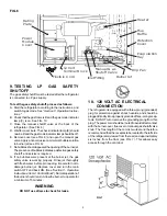
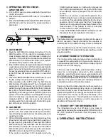
9. TESTING LP GAS SAFETY
SHUTOFF

The gas safety shutoff must be tested after the refrigerator
is connected to LP gas supply.

To test the gas safety shutoff, proceed as follows:
A. Start the refrigerator according to the instructions, and

switch to gas mode. See "

Section C. Operation Instruc-

tions."

B. Check that the gas flame is lit and the gas mode indicator

lamp (C) is on. See FIG. 10.

C. Close the manual shutoff valve at the back of the

refrigerator.  (See FIG. 6)

D. Wait for one minute. The check indicator lamp (E) should

now be lit and the gas mode indicator lamp should be off.

E. Remove cover (see FIG. 6) and open the manual gas

valve. Apply a noncorrosive commercial bubble solution
to burner jet (see FIG. 6).

F. No bubbles should appear at the opening of the burner jet.

The presence of bubbles indicates a defective gas safety
shutoff, and service is required.

G. If no bubbles were present at the burner jet, the gas

safety valve is working properly. Rinse jet thoroughly
with fresh water before proceeding. Be careful not to
damage burner jet. Replace cover and turn the main
switch OFF and back ON. (See "

Section C. Operation

Instructions, Item 2. Control Panel"). Normal operation of
the burner should return. Allow the burner to operate for
a minimum of 5 minutes.

WARNING

DO NOT use a flame to check for leaks.

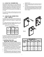
10. 120 VOLT AC ELECTRICAL

CONNECTION

The refrigerator is equipped with a three-prong (grounded)
plug for protection against shock hazards, and should be
plugged directly into a properly grounded three-prong recep-
tacle. DO NOT cut or remove the grounding prong from this
plug. The power cord should be routed to avoid direct contact
with the burner cover, flue cover or manual gas shutoff valve
knob. The free length of the cord is two feet and therefore
recommended that the receptacle be located to the left side
of the refrigerator (viewed from the rear) and approximately
six inches from the floor (see FIG. 7). This allows easy
access through the vent door.

FIG. 7

Flexible C ord

12 V olt
Terminal B lock

Inlet F itting

Manual G as
Shutoff V alve

Burner Jet

Drip P an

Evaporation
Tray

Protection
Cover

Flue
Baffle

Heater

Power
Module
Cover

Rating
Plate

FIG. 6

Содержание RM2607

Страница 1: ...OR YOUR SAFETY Do not store or use gasoline or other flammable vapors and liquids in the vicinity of this or any other appliance WARNING Improper installation adjustment alteration service or maintena...

Страница 2: ...e however contingent on the installa tionbeingmadeinaccordancewiththefollowinginstructions as applicable In the U S A the installation must conform with 1 National Fuel Gas Code ANSI Z223 1 latest edi...

Страница 3: ...ator and the wall behind the refrigerator NOTE Clearance N isthedistancebetweenthebottom of the lower vent to the roof material For ventilation height refertoSectionA Installation Item5 Ventilation He...

Страница 4: ...equence in securing refrigerator in enclosure can cause leakage between the frame and cabi net The plastic caps are snapped in the front base to cover the screw heads and the decoration strip is secur...

Страница 5: ...oceeding Be careful not to damage burner jet Replace cover and turn the main switch OFF and back ON See Section C Operation Instructions Item2 ControlPanel Normaloperationof the burner should return A...

Страница 6: ...nded wire sizes are shown below MAXIMUM TOTAL CONDUCTOR WIRE LENGTH In Feet and Meters RM RM AWG 2607 2807 215W 215W 10 17 FT 17 FT 5 M 5 M 8 27 FT 27 FT 8 M 8 M Thewiresfromthebatterytotherefrigerato...

Страница 7: ...Plastic caps for the empty holes are in the parts bag Remountthedoorsandthehingepinsinthereverseorderof theirremoval Unscrewthehandlesandrefastenthemonthe opposite side of the door Insert the plastic...

Страница 8: ...be leveled only so it is comfortable to live in no noticeable sloping of floors or walls When the vehicle is moving the leveling is not critical as the rolling and pitching motion of the vehicle will...

Страница 9: ...o the OFF then ON position If the control is switched to AC operation while the CHECK indicator lamp is on it will function properly but the CHECK indicator lamp will not go off until the main power O...

Страница 10: ...n ON position If the control is switched to AC or DC operation while the CHECK indicator lamp is on it will function properly but the CHECK indicator lamp will not go off until the main power ON OFF b...

Страница 11: ...d in direct contact with the freezer shelf Toreleasetheicecubes seizethetraywithbothhandsand twist the tray Cubes not required should be replaced in the tray Refill the tray with water and replace the...

Страница 12: ...per vent and area between these openings for any obstructions such as bird insect nests spider webs etc Clean the coils on the back of the refrigerator Use a soft bristled brush to dust off the coils...

Страница 13: ...lue cap 8 Clean burner tube with a brush Blow out burner with compressedair 9 Beforeremovingburnerjet cleanburnerareaofsoot andscalethatfelloutoffluetube Removetheburner jet Soak the jet in wood alcoh...

Страница 14: ...rized service center for parts and repairs as needed F FUSES The2 wayAMESmodelsareequippedwith2fuses onefor the refrigerator control system and one for the AC cartridge heater The 3 way AMES models ar...

Отзывы: