6
bottom frame (5).
D.
Between the upper edge of the panel and door frame
there is a gap which should be covered by the decora-
tion strip.
E.
Put the decoration strip across the door so that the gap
is covered and push it upward (6). The tabs on the inside
of the strip should fit behind the flange of the door frame.
Secure the decoration strip with the two screws re-
moved in Step A.
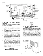
11. 12 VOLT DC CONNECTION
All refrigerator models require a 12 volt DC supply (even
though 2-way models are designed to operate on 120 volts
AC and gas, a 12 volt DC control is required to maintain the
automatic energy system). The DC lead connections are at
terminals located at the rear of the refrigerator. (See FIG. 6).
One lead is marked positive (+) and the other negative (–).
Correct polarity must be observed when connecting to the
DC supply.
Do not use the chassis or vehicle frame as one of the
conductors. Connect two wires at the refrigerator and route
to the DC supply.
12. 12 VOLTS DC CONNECTION
3-WAY MODELS
The distance the current must travel from the battery to the
refrigerator dictates the AWG wire size to be used. Should
the wire be too small for the distance, a voltage drop will
result.
The voltage drop affects the wattage output of the 12 volt
cartridge heater and resultant refrigerator performance. Rec-
ommended wire sizes are shown below.
MAXIMUM TOTAL CONDUCTOR WIRE LENGTH
(In Feet and Meters)
RM
RM
AWG
2607
2807
215W
215W
10
17 FT.
17 FT.
5
M
5
M
8
27 FT.
27 FT.
8
M
8
M
The wires from the battery to the refrigerator must be of large
enough size to handle the load. The connections must be
clean, tight and free from corrosion. If not, a resulting voltage
drop will cause a decreased cooling capacity.
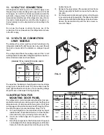
13. INSTRUCTION FOR
MOUNTING DOOR PANEL
The refrigerator is normally delivered without the door pan-
els. Before starting the mounting work, check that the panel
dimensions are in compliance with those given in the Table
on this page and the instructions are read thoroughly. When
mounting the panel, proceed as follows. (See FIG. 8)
A.
On new refrigerators, the decoration strips are taped
inside the door. If installed on the door, remove the door
decoration strip (2) by removing its two screws (1).
B.
Insert one vertical edge into the groove of the door
frame (3).
C.
Bend the panel gently so that the free side of the panel
can be slipped into the corresponding groove of the door
frame (4). Slide the panel down into the groove of the
Refr. Models HEIGHT WIDTH
TYPE
MAX.
MIN.
MAX.
MIN.
RM2607
upper
mm
317
314
496
493
inch 12-15/32
12-3/8
19-17/32
19-13/32
lower
mm
830
827
496
493
inch 32-11/16
32-9/16
19-17/32
19-13/32
RM2807
upper
mm
389
386
544
541
inch
15-5/16
15-3/16
21-13/32
21-19/64
lower
mm
908
905
544
541
inch
35-3/4
35-5/8
21-13/32
21-19/64
PANEL DIMENSIONS
MAX. THICKNESS 5/32" (4 mm)
1
1
1
1
2
3
4
5
6
FIG. 8

