background image

13

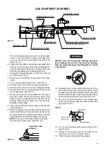
The correct operating pressure is 11 inches of water

column. The correct place to take the LP gas pres-

sure is at the test port just ahead of the burner jet.

(See FIG. 12).

E. Inspect the flue baffle. It should be reasonably clean

and free of soot. Heavy soot formation indicates im-

proper functioning of the burner. The flue and burner

both require cleaning in the following manner:

1. Unplug the refrigerator power cord from the 120 volt

AC outlet. (See FIG. 3).

2. Disconnect or shut off the 12 volt power to the refrig-

erator.

3. Turn manual shutoff valve to OFF. (See FIG. 1).
4. Remove cover from the burner housing. (See FIG. 1).
5. Disconnect the wire from the high voltage electrode.
6. Remove the burner mounting screws and remove the

burner assembly. (See FIG. 12).

7. Remove the wire and the flue baffle from the top of

flue tube. Clean the flue from the top using a flue

brush. Blowing compressed air into the flue will not

properly clean soot and scale out of the flue tube.

Replace the flue baffle.

8. Clean burner tube with a brush. Blow out burner with

compressed air.

9. Before removing burner jet, clean burner area of soot

and scale that fell out of flue tube. Remove the burner

jet. Soak the jet in wood alcohol and blow it out with

compressed air. Reinstall and tighten burner jet.

NOTE:

 The color of the flame shall be clear blue

over the slots of the burner. (See FIG. 13).

DO NOT use a wire or pin when cleaning the burner

jet as damage can occur to the precision opening.

This can cause damage to the refrigerator or create

a fire hazard.

! WARNING

10. Reinstall burner, being careful that the end of the

burner fits into the slot on the burner bracket. Check

to make sure slots are centered under the flue tube

and the thermocouple is positioned properly (tip of

thermocouple extends over two slots of burner).

11. Be sure to reconnect the wire to high voltage elec-

trode. Check the electrode for proper location and

gap. (See FIG. 14).

12. Turn on manual gas shutoff valve and check all fit-

tings for leaks.

13. Connect 120 volt power cord to the outlet and re-

connect or turn on the 12 volt DC power.

14. Check LP gas safety shutoff. See page 6.

FIG. 13

Clear blue color

of flame

FIG. 14

Electrode

Burner tube

1/8” to 3/16”

(3-5 mm)

GAS EQUIPMENT ASSEMBLY

SOLENOID VALVE

 INLET FITTING

 MANUAL SHUTOFF VALVE

 Shown in open position

 PRESSURE TEST PORT

  BURNER JET

  SPARK ELECTRODE

BURNER TUBE  .

THERMOCOUPLE

BURNER MOUNTING

SCREWS

FIG. 12

Содержание NDR1492-B

Страница 1: ...stance or additional information consult a qualified installer service agency or the gas supplier AVIS Cet appareil doit tre r par seulement par un r parateur autoris Modification de l appareil pourra...

Страница 2: ......

Страница 3: ...or Button 4 Climate Control Button 5 Low Ambient Control Button A AC Mode Indicator Lamp B AES AUTO Mode Indicator Lamp C GAS Mode Indicator Lamp D CHECK Indicator Lamp E Temperature Indicator Lamps F...

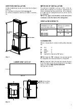
Страница 4: ...led and used without modification An opening toward the outside at floor level in the refrigera tor compartment must be provided for ventilation of heavier than air fuel gases The lower vent of the re...

Страница 5: ...be sealed Make sure that there is a complete seal between the front frame of the refrigerator and the top sides and bottom of the enclosure A length of sealing strip is ap plied to the rear surface o...

Страница 6: ...as safety shutoff must be tested after the re frigerator is connected to LP gas supply To test the gas safety shutoff proceed as follows 1 Start the refrigerator according to the instructions and swit...

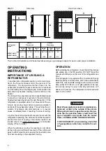
Страница 7: ...r coil at the back of the refrigerator VENTILATION HEIGHTS CLEARANCES Minimum clearances in inches to combustible materials are G Top 0 K Side 0 L Bottom 0 M Rear 0 N See NOTE Clearance N below NOTE C...

Страница 8: ...f the vehicle will pass to either side of level keeping the liquid ammonia from accumulating in the evaporator tubing OPERATION Before starting the refrigerator check that all the manual gas valves ar...

Страница 9: ...as automatically switched to the GAS mode 2 If the CHECK indicator lamp D illuminates and the GAS mode indicator lamp C is off the controls have failed to ignite the burner in the GAS mode GAS operati...

Страница 10: ...imes If repeated attempts fail to start the LP gas operation check to make sure that the LP gas supply tanks are not empty and all manual shutoff valves in the lines are open If the problem is still n...

Страница 11: ...he ice is formed Food in the fresh food compartment may be frozen if the setting is left on COLDEST posi tion DEFROSTING Shut off the refrigerator by pressing the main power ON OFF button to the UP OF...

Страница 12: ...ar with LP gas systems and refrigerators 1 REFRIGERATOR REMOVAL Before working on the refrigerator make sure the AC voltage and DC voltage leads are disconnected Shut off the gas supply Disconnect the...

Страница 13: ...ea of soot and scale that fell out of flue tube Remove the burner jet Soak the jet in wood alcohol and blow it out with compressed air Reinstall and tighten burner jet NOTE The color of the flame shal...

Страница 14: ...e not responsible for any failures caused by improper adjust ments and unfavorable installation conditions Contact service point or distributor service dept for assistance Replacement Parts Suppliers...

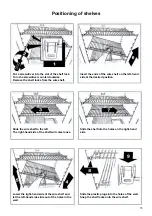
Страница 15: ...e of the shelf will come loose Lower the right hand side of the wire shelf and let the left hand side slide out of the holes in the wall Slide the plastic plugs into the holes of the wall Snap the she...

Страница 16: ...16 MO FO 0222...

Отзывы: