background image

3311145.000 Secondary Burner Housing Kit Service Instructions

8

{

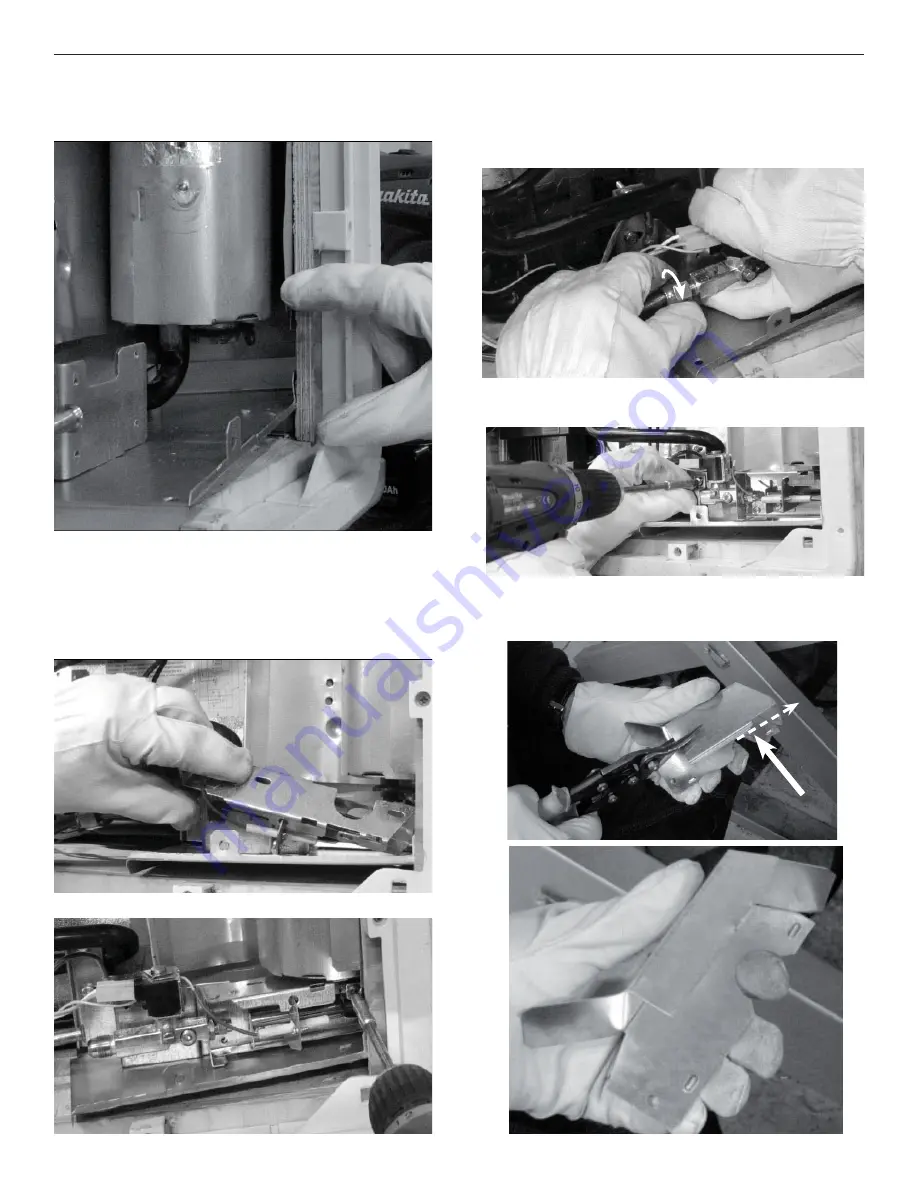
Step 11.  In the unlikely event that the burner 

needed to be removed, reinstall burn-
er at this step. Fasten only the right 
most screw fi rst using one of the fi ve 
(5) screws saved in step 6.

Step 12.  Reconnect the LP gas line if you have 

removed it as part of this installation. 
Be sure to use a back up wrench to 
properly secure supply line to gas 
valve.

Step 13.  Secure the burner with the remaining 

four (4) screws from step 6.

Step 14.  If necessary, trim the bottom of the 

burner cover using a pair of metal 
shears as shown. 

 Leave 

suffi cient spacing to enable the 

reinstallation of the burner, if burner 
removal was necessary.

Step 10

Step 10

Step 11

Step 11

Step 11

Step 11

Step 12

Step 12

Step 13

Step 13

Discard this piece of
 the burner cover.

Step 14

Step 14

Step 14

Step 14

Содержание 3311145.000

Страница 1: ...N3T 5L8 CANADA 519 720 9578 For Service Center Assistance Call 800 544 4881 3311145 000 KIT SECONDARY BURNER HOUSING ASSEMBLY FOR Americana AMES AES 2 Way Refrigerators MODELS RM2652 RM2662 RM3662 RM2852 RM2862 RM3862 NDR1062 Serial Numbers Dometic LLC recall campaign numbers 06E 076 and 08E 032 Patent Pending 713xxxxx through 752xxxxx 301xxxxx through 319xxxxx 801xxxxx through 852xxxxx 320xxxxx t...

Страница 2: ...y Indicates a potentially hazard ous situation which if not avoided may result in minor or moderate injury When used without the safety alert symbol indicates a potentially hazardous situation which if not avoided may result in property damage Read and follow all safety information and in structions These instructions must be read and under stood before installation of this kit This kit must be in...

Страница 3: ...ection plate bottom plate boiler cover rear cover holder for thermal fuse and cover for the heating element Furthermore it explains how to install the thermo disc and how to connect the thermal fuse and wire on units operating on LP gas and 120 VAC energy sources These units are called 2 Way refrigera tors Depending on how the refrigerator s ventilation grille is mounted this Service Kit may be in...

Страница 4: ... 7 If loosening or removal are required con tinue with step 2 The bottom plate has two score lines on it You may need to shear the bottom plate off at these locations to get it to fit on units that already have a sheet metal barrier under the burner Note Make sure the tabs identified with arrows in the photo below are facing up Explosion hazard LP gas ignition could occur Shut off the LP gas suppl...

Страница 5: ...ing screws Save for reinstallation Step 7 Slide bottom plate Item 2 into posi tion Edge with the two 2 mounting tabs will go toward you Tabs should be up See Step 1 photo One end of the bottom plate should rest on the top of the refrigerator leg The bottom plate has two score lines on it Although most units will not re quire modification you may need to shear the bottom plate off at these location...

Страница 6: ...backside of the refrigerator cabi net It goes all the way to the bottom and side of the refrigerator Slide the edge in between the frame and cabi net Make sure to place it behind the liquid temperature exchanger Liquid Temperature Exchanger Tube Step 9 Fold the existing back cover toward the protection plate Back cover Step 8 Step 8 Step 8 Step 8 Step 8 Step 8 Step 8 Step 8 Step 9 Step 9 ...

Страница 7: ...nd form a circle approximately 6 inches in size Note that additional adjust ments to the exact form of the boiler cover may be necessary This will allow you to slide the cover around the cooling unit flue jacket If required pull the leading edge of cover from behind the cooling unit flue jacket using a pair of long needle nose pliers or by inserting a 6 plas tic tie wrap into the clearance hole on...

Страница 8: ... of this installation Be sure to use a back up wrench to properly secure supply line to gas valve Step 13 Secure the burner with the remaining four 4 screws from step 6 Step 14 If necessary trim the bottom of the burner cover using a pair of metal shears as shown Leave sufficient spacing to enable the reinstallation of the burner if burner removal was necessary Step 10 Step 10 Step 11 Step 11 Step...

Страница 9: ...ation of the burner cover easier Step 16 Put the cover back in place Step 17 Reinstall the cover screw Step 18 Rebend tab to its original form Step 19 Readjust the flue jacket to rest on top of burner cover Adjust new boiler cover to rest inside the bottom plate at the bottom of refrigerator Step 14 Step 14 Step 15 Step 15 Step 16 Step 16 Step 16 Step 16 Step 17 Step 17 Step 18 Step 18 Step 19 Ste...

Страница 10: ...a certified gas technician conduct a pressure DROP leak test on the LP gas sys tem per approved industry standard Personal injury hazard If the RV continues to in dicate a gas leak by the decay of a manometer the leak must be repaired before the gas system is allowed to be left on Do not operate the RV with an LP leak at any location on the system Step 24 Skip this step for integrated ignition mod...

Страница 11: ...t is larger it is a non universal or integrated ignition power module See Step 41 on how to measure the cover Step 26 Step 26 Step 27 Connect the uninsulated end of the thermal fuse Item 13 to the positive connection on the back side of 12 VDC terminal block Step 27 Step 27 Step 27 Step 27 Step 28 If a thermo disc is not already present on the flue jacket install the thermo disc Item 7 using two p...

Страница 12: ...use Item 13 in the thermal fuse holder Item 3 and make sure the sensor is located as shown in the photo The thermal fuse should extend outside the securement tab by 1 2 Sensor Step 30 Step 30 Step 29 Step 29 Step 29 Step 29 Step 28 Step 28 Step 29 Connect the end of the thermal fuse with the insulated flag to one side of the thermo disc 1 2 ...

Страница 13: ...ace Step 32 Step 32 Step 32 Step 32 Step 34 Connect the provided wire Item 12 to the other terminal on the thermo disc Step 34 Step 34 Step 35 If the power module cover was re moved snap it back in place Replace the screw Step 35 Step 35 Step 33 Step 33 Step 33 Using a pair of pliers connect one end of the supplied wire Item 12 to the J4 or T4 terminal on non universal power modules and J1 on univ...

Страница 14: ...r for the heating ele ment Item 4 Start by forming the cover a to fit into place b Insert the left tab and then the right c Press in with your fingers to make the cover fit as intended d a Step 36 Step 36 Step 36 Step 36 b Step 36 Step 36 c Step 36 Step 36 Step 36 Step 36 d Step 36 Step 36 ...

Страница 15: ...cation on the system Step 37 Step 37 Step 38 Step 38 Step 38 Wipe dry with a paper towel Step 40 Install the rear cover Item 6 Align the holes in the boiler cover and the holes in the bottom plate with the rear cover holes and secure with two 2 8 x 3 8 screws Item 11 and two 2 8 x 1 2 screws Item 10 Install the bottom corner fastener first with one 1 of the 8 x 1 2 screws and then the other 8 x 1 ...

Страница 16: ...wer module use wiring diagram 3311221 000 If it is larger than 4 inches in height use 3311211 000 non universal power module or 3312755 000 integrat ed ignition power module based on whether you removed the power mod ule cover to complete the connections If you did not remove the cover it is an integrated ignition power module 3312755 000 This measurement in cludes the mounting tab Rear cover must...

Страница 17: ...t appliances and components found on RVs was something that I always had a desire to create I hope this resource makes your RV repairs easier as it has mine but please be careful and follow proper safety practices when attempting to repair your own RV If in doubt please consult with a professional RV technician All service manuals provided on www myrvworks com are believed to be released for distr...

Отзывы: