3
Table 1 - Oil Dam and COL to Shaft Clearance (Inches)
Shaft Diameter
2-15/16 3-17/16 3-15/16
4-7/16
4-15/16 5-7/16
Tip of oil dam to shaft
5/32
5/32
1/8
1/8
1/8
1/8
Shaft Diameter
6
7
8
9
10
12
Tip of oil dam to shaft
11/32
11/32
9/32
9/32
1/2
1/2
Tip of COL to shaft
1/4
5/16
5/16
5/16
5/16
13/32
3. INSTALLATION OF OIL RING (S)
Each ring is match marked and MUST NOT be interchanged.
Place oil ring(s) around lower liner and shaft. Install and tighten
four screws in each oil ring.
Oil dams can be adjusted, if necessary, to avoid contact with
oil ring. Loosen screws and move dam; bend base of dam, if
necessary, to obtain clearance in Table 1.
Oil shaft under oil ring(s). Make sure oil ring(s) rotate freely.
FOR BORES 6” THROUGH 12”:
Narrow leaf of COL will contact
oil ring inside wide groove as shown below. COL can be adjusted
to align leaf with wide oil ring groove. Loosen screws and move
COL; do NOT bend or distort COL. Tighten screws.
4. NON-EXPANSION BEARINGS WITH DODGE SPLIT
THRUST COLLARS (‘S’ LINERS ONLY)
Split thrust collars are available for ‘S’ liners only. Remove clamp
screws from collars. Remove jam screws and back out set
screws so they do not protrude into inside diameter of collar.
MATCH
MARKS
PART NO.
Place one half of collar on shaft with large chamfer next to shaft
shoulder. Rotate collar half around shaft and place other half in
position.
LARGE CHAMFER
NEXT TO
SHAFT SHOULDER
NOTE: Collar halves are match marked; do NOT assemble
halves with different marks.
Tighten clamp screws to torque specified in Table 2. Collar faces
MUST NOT be offset at split. Repeat for second collar.
Locate collars tight against shaft shoulders. This will allow
0.015
to
0.035 inch
total running clearance between collars and liner thrust
faces. Tighten set screws to torque specified in Table 2. Install and
tighten jam screws on top of set screws.
Table 2 - Torque Values for DODGE Split Thrust Collars (in.-lbs.) ft.-lbs.
Shaft Size
(inches)
2-15/16
3-7/16
3-15/16
4-7/16
4-15/16
5-7/16
Clamp
Screw
(96) 8
(96) 8
(96) 8
(96) 8
(204) 17
(204) 17
Set
Screw
(60) 5
(60) 5
(60) 5
(60) 5
(132) 11
(132) 11
Shaft Size
(inches)
6
7
8
9
10
12
Clamp
Screw
(360) 30
(360) 30
(900) 75
(900) 75 (1800) 150
(1800) 150
Set
Screw
(264) 22
(264) 22
(264) 22
(264) 22 (1320) 110
(1320) 110
Содержание SLEEVOIL RXT
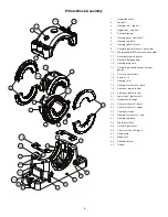
Страница 9: ...9 Oil Ring Assembly 22A 22B 22C...
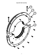
Страница 10: ...10 Labyrinth Seal Assembly 19C 19A 19D 19B...
Страница 11: ...11 Shim Collector Oil Leaf Oil Dam...

