


Digital Monitoring Products
XTLN/XTLN-WiFi Installation Guide
6
InstallatIon
On-Board 1100 Series Wireless
12.1 Wireless Antenna
The XTLN/XTLN-WiFi Wireless Antenna is integrated into the circuit board. The panel’s built-in wireless
receiver operates with DMP 1100 Series transmitters. See section 3.1 for a list of accessory devices.
12.2 Wireless LED Operation
Green (TX):
The green LED flashes every time the receiver transmits (32 times per second). If the panel
is reset, or the panel is powered off, the green LED is off. Under normal operation, the green LED flashes
constantly with no interruption or change.
Yellow (RX):
The yellow LED flashes every time the panel receives a message from a programmed wireless
transmitter. When a message is sent by a transmitter, typically by pressing or releasing the tamper switch,
the yellow LED should flash indicating that the panel received a message from the transmitter. If the LED
never flashes, the transmitter is not getting through to the panel. This could be because of a misprogrammed
serial number or the transmitter is too far away. Under normal operation, the yellow LED flashes at every
trip of every wireless transmitter and when the transmitters perform their periodic check-in. It is not
unusual for this LED to stay off for many minutes at a time when no transmitters are communicating.
Wireless Keypads
13.1 Mounting Keypads
DMP keypads have removable covers that allow the base to be mounted on a wall, desk stand or other flat
surface using the screw holes provided on each corner.
13.2 Wireless Keypad Association
Enable Wireless Keypad Association operation on both the keypad and panel.
To enable association operation in the keypad, access the Installer Options Menu (3577 (INST)). The keypad
logo LEDs turn off until association is successful. Refer to 9000 Series Wireless Keypad Installation Guide
LT-1107 or the 9862 Series Wireless Graphics Keypad Installation Guide LT-1367 for more information.
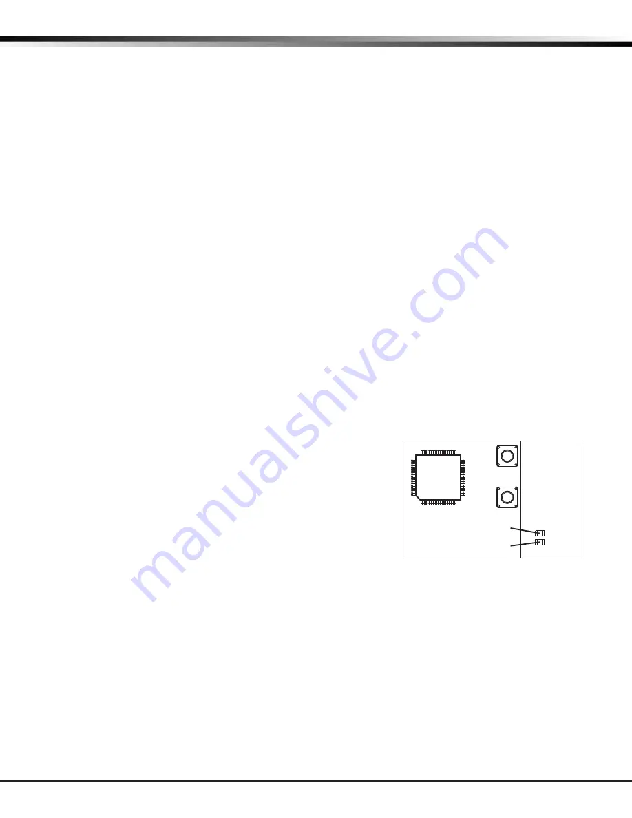
To enable association in the panel, reset the panel three times as described below and observe the operation
of Green LED and Red Backlit Logo LED’s. See Figure 5 for Backlit Logo LED location.
1.
Press RESET.
2. The Green LED turns off.
3. The Green LED and Red LED turn on steady then off.
4. The Green LED turns on again.
Repeat steps 1 - 4 two more times or until both the Green LED and
Red LED remain on steady.
For 60 seconds the panel listens for wireless keypads that are in the
Installer Options Menu (3577 CMD) and have not been programmed,
or associated into another panel. Wireless keypads are assigned to
the first open device position automatically based upon the order in
which they are detected. The keypad logo turns Green to indicate it
has been associated with the panel.
Wireless Zones
14.1 Description
XTLN/XTLN-WiFi panels provide 28 wireless zones numbered 1 to 28. A default zone name, zone type, and
area assignment are described in the XTLN/XTLN-WiFi Programming Guide (LT-1221) and can be changed in
Zone Information programming as needed. The defaults are provided as a programming convenience to help
reduce installation time.
Wireless Key Fobs and Outputs
15.1 Description
XTLN/XTLN-WiFi panels provide 8 wireless key fob or output addresses numbered 31 to 34 and 41 to 44.
A default name is provided as a programming convenience to help reduce installation time. The default
names are described in the XTLN/XTLN-WiFi Programming Guide (LT-1221) and can be changed in Output
Information or Zone Information programming as needed.
+
_
RESET
S1
LOAD
S2
BAT
J1
PROG
RED
PWR
MODEL XTL
TX RF RX
S
N
CR7
CR6
Red LED
Green LED
Figure 5: XTLN/XTLN-WiFi Backlit
Logo LED’s
Содержание XTLN
Страница 1: ...Inst alla tion Guide XTLN xtln WiFi Panel...


