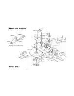
BODY ROMOVAL ZTR 422 - 424
1. Disconnect throttle cable from engine.
2. Remove four (4) control lever bolts and remove upper control
levers.
3. Remove engaging handle by removing bolt and nut under
handle.
4. Remove the two (2) attach nuts on floor of body and two (2)
sheet metal screws at the rear of body.
5. Disconnect the rear wiring loom from the body by lightly
squeezing the Econo-Seal plug. This plug is located at the
left rear of the body.
6. Note: Loosen bolts that hold safety switch (P/N 4079) mount
plate and slide switch away from engaging rod. Tighten one
bolt just enough to hold switch in this position until body is
reassembled.
7. Place height adjustment lever in vertical position and care-
fully lift body up and off of chassis.
8. Reverse the above procedure for assembly.
Note: With the mower deck in the engaged position slide
the switch bracket toward the engag ing rod (P/N 6087-1)
until the switch leaf just makes contact with the switch
button. Tighten both bolts in switch bracket. With the mower
deck engaged, attempt to start engine in all cutting height
positions. If engine starts in any cutting height positio n
readjust the switch. Disengage the mower deck and start
the engine in each cutting height position. If engine fails to
start in any cutting height position readjust switch. With
operator in normal mowing position engage mower deck
and remove weight from seat. The engine should die.
Repeat this procedure in each cutting height position.
CHAIN DRIVES
ADJUSTMENT
To adjust the drive chains, the body must be removed and
shims added behind the transaxle. Loosen 4 bolts which
hold the transaxle to the frame. Insert shims as needed for
adjustment between transaxle and mount plates. When
properly adjusted, the slack span at the mid -point of the
chain should have a total possible movement perpendicular
to the chain of about 9/16". Tighten the 4 bolts which hold
the transaxle to the frame. Replace chain when rollers
become loose, chain breaks, or chain fails to operate pro -
perly.
LUBRICATION
1. Chains: Proper lubrication is important for effective
roller chain operation. Use high quality lubricating oil (do
not use grease or extra heavy oil) and apply drops of oil
to the chain joints every 10-15 hours of operation.
2. Front Caster Assembly: Each caster assembly has a
grease fitting located on the underside of the bearing.
For best results, use any good multi-purpose grease
every 1 0 - 1 5 hours of operation.
3. All other Bearings: All other bearings on your mower
are sealed and require no lubrication.
WHEELS AND TIRES
Correct tire pressure is essential to the correct operation of
the machine. The correct pressure for the drive tires is 8-10
Ibs. The front tires should be inflated to 20-24 Ibs. Lug nuts
should be checked periodically.
Содержание ZEETER 422 & 424
Страница 1: ...OPERATOR S MANUAL...
Страница 4: ...ALWAYS SET PARKING BRAKE AND DISENGAGE BLADE OPERATION BEFORE DISMOUNTING...
Страница 9: ......
Страница 10: ......
Страница 11: ...10...
Страница 12: ......
Страница 13: ......


