ALWAYS DISENGAGE BLADE OPERATION BEFORE
DISMOUNTING.
9. Parking Brake:
Parking brake is on right hand side of floor area and is
engaged by pushing full forward with foot. To disengage,
pull lever back toward operator by hand. In emergency
situations, brake may be used in conjunction with the
natural braking of the transaxle by applying pressure with
foot. Always set parking brake before dismounting. Be sure
that parking brake is disengaged before moving.
MAINTENANCE
BEFORE PERFORMING ANY MAINTENANCE, SHUT
OFF ENGINE, ALLOW TO COOL AND DISCONNECT
SPARK PLUG.
ENGINE
For complete engine operating and maintenance informa-
tion, refer to engine operating and maintenance instructions
furnished by the engine manufacturer and supplied with
each mower.
BATTERY
Procedure for initial activation of battery:
1. Fill with electrolyte solution to lower ring of battery.
2. Let stand for 30 minutes.
3. Charge at 4 amps for 3 hours or 1 amp for 12 hours.
4. After initial filling, fluid level may be maintained with distilled
water.
Procedure for off-season storage:
1. Charge battery.
2. Disconnect cables from battery terminals. Identify cables so
that they may be easily reconnected to the correct
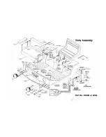
terminal. (See also wiring diagram shown on Body Assembly
illustration.)
3. Clean top of battery and terminals.
4. Do not remove battery from mower.
5. To reactivate, reconnect cables to correct terminals and
charge battery if needed.
BELT ADJUSTMENT
The best tension for a V -belt drive is the lowest tension at
which the belts will not slip under normal load condition. Check
the tension on a new belt frequently during first hours of
operation and every 10-15 hours or monthly thereafter. Too
much tension shortens belt and bearing life. Too little tension
causes slippage and loss of power. Be sure that belts and
pulleys are kept free of foreign material. If belt slippage occurs,
tighten it just enough to prevent slippage.
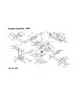
TRANSAXLE DRIVE BELT
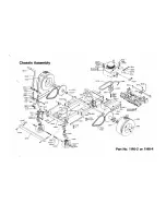
To adjust tension, loosen four (4) bolts which hold engine to
mount and belt keeper in place. Adjust tension bolt (located at
rear of chassis) until desired tension is achieved. Do not over
tighten. Tighten four (4) bolts holding engine.
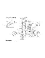
MOWER DRIVE BELT
Belt tension for mower drive belt is adjusted by loosening nut
on mower deck turnbuckle assembly and turning turnbuckle to
achieve desired tension. Retighten nut. Tension should be
checked with belt in engaged position.
REPLACE BELTS WHEN ADJUSTMENT CAN NO
LONGER BE MADE SATISFACTORILY OR IF BELTS BE-
COME WORN.
Содержание ZEETER 422 & 424
Страница 1: ...OPERATOR S MANUAL...
Страница 4: ...ALWAYS SET PARKING BRAKE AND DISENGAGE BLADE OPERATION BEFORE DISMOUNTING...
Страница 9: ......
Страница 10: ......
Страница 11: ...10...
Страница 12: ......
Страница 13: ......


