background image


<:>                '     I


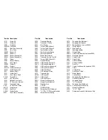
PARTS LIST FOR 42" MODELS


Part No.             DescriptionPart No.             Description                        "      Part No.             Description


1000C  Frame Weldment 

1581 

Brake Pedal Arm Weldment 

4006-9 Battery - Ground Cable


1014  Caster Pipe Nipple 

1591 

Brake Pedal Pin                                     

4007-1   12 V Battery


1015  Caster Weldment 

1606 

Brake Mount Weldment 

4008     Solenoid


1020  Caster Axle 

1624 

Oil Drain Assembly 

4009     Wire Clip (not shown)


1022  Caster Wheel & Tire 

1629 

Bumper Weldment 

4011-1  Name Decal, 42"


1022A  Caster Wheel Bearing 

1635 

Double Engine Pulley 

4013     Wire Tie


1039  Lower Lift Link 

1636 

Bellcrank Kit 

4014     Seat, ZTR 422


1043  Battery Strap 

1638 

Lower Control Lever Assembly                   

4014A   Seat Assembly (includes 4054)


1093  Tie Bar Assembly 

1643 

Brake Pedal                                   

4022     Ground Terminal                            


1094  Tie Bar 

1645 

Seat Bracket 

4025     Switch Decal


1095  Caster Weldment Assembly                        1646 

Weight Brace 

4049     Model Decal, ZTR 422


1501R  Upper Control Lever R 

1647 

Control Pin (replaces 1604) 

4050     Body, ZTR 424


1501L  Upper Control Lever L 

2091 

Tension Bracket 

4051      Body, ZTR 422


1502  Control Rod Assembly 

2221 

Transaxle Shim 16 ga. 

4054     Seat Switch Assembly


1503  Wheel Hub Assembly             

2222 

Transaxle Shim 22 ga. 

4058     Arm Rest Bracket R


1504  Wheel Hub 

2436 

Switch Decal 

4059     Arm Rest Bracket L


1506  Hub Flange 

3029 

Front Grommet 

4060     Arm Rest


1507-1  Wheel/Hub Bearing 

3059 

Spring Wire Clip 

4065     Model Decal, ZTR 424


1509  Rear Wheel & Tire 

3502 

Hand Grip 

4067     Ignition Switch


1535  Drive Chain 

3504 

Double BallJoint 

4067A   Switch Key (for 4067)


1536  Chain Connecting Link 

3507 

Floor Pad - Long 

4069     Seat Bottom


1539  Transaxle Drive Belt 

3508 

Floor Pad - Short 

4070     Seat Back


1540  Engine Shaft Key 

3511 

Adhesive Bumper 

4071      Seat Assembly


1543  Lift Knob 

3521 

Engaging Cam Mount Bushing 

4075      10 AMP Fuse (not shown)


1544  Bellcrank Assembly 

3531 

Decal - Operating Instructions 

4076     Headlight Assembly


1552  Belt Keeper Weldment 

3532 

Decal - Blade Drive 

4079     Body Switch


-     1560-1  Battery Splash Guard 

3533 

Decal - Cutting Height 

4083     Switch Bracket - Switch Section


1564  Brake Arm Weldment 

3534 

Decal - Parking Brake (42")                     

4092     Fuse Holder


1574  Brake Pivot Weldment 

4005B 

Throttle Cable 

4093     Body Wiring Loom


1579  Short Brake Rod 

4006-2 

Solenoid - Starter Cable 

4109     Rear Wiring Loom


1580  Long Brake Rod 

4006-8 

Solenoid - Battery Cable 

4112     Body Wiring Loom


Содержание ZEETER 422 & 424

Страница 1: ...OPERATOR S MANUAL...

Страница 2: ...parts which within the warranty period shall be shown to be defective due to faulty workmanship or materials at the factory All parts claimed defective must be returned to the factory for inspection...

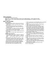
Страница 3: ...ays mow at the slowest speed that will cut satisfactorily 5 Keep hands and feet away from the blade at all times 6 Although the Dixon mower is equipped with a missile deflector keep persons clear of t...

Страница 4: ...ALWAYS SET PARKING BRAKE AND DISENGAGE BLADE OPERATION BEFORE DISMOUNTING...

Страница 5: ...ontrol braking turning direction and acceleration TO GO FORWARD From neutral position gently push both drive levers forward to increase speed move levers further forward TO GO BACKWARD From neutral po...

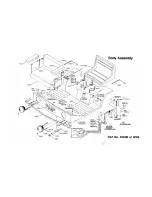
Страница 6: ...may be easily reconnected to the correct terminal See also wiring diagram shown on Body Assembly illustration 3 Clean top of battery and terminals 4 Do not remove battery from mower 5 To reactivate re...

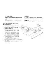
Страница 7: ...on readjust switch With operator in normal mowing position engage mower deck and remove weight from seat The engine should die Repeat this procedure in each cutting height position CHAIN DRIVES ADJUST...

Страница 8: ...with a rollpin through the engaging cam 3 Position the drive belt on pulleys 4 Place mower deck under unit in approximate operating position with engaging rod through hole in the floor 5 Connect driv...

Страница 9: ......

Страница 10: ......

Страница 11: ...10...

Страница 12: ......

Страница 13: ......

Страница 14: ...axle Shim 16 ga 4054 Seat Switch Assembly 1503 Wheel Hub Assembly 2222 Transaxle Shim 22 ga 4058 Arm Rest Bracket R 1504 Wheel Hub 2436 Switch Decal 4059 Arm Rest Bracket L 1506 Hub Flange 3029 Front...

Страница 15: ...09R Cradle R 5061L HD Support Assembly L 6107 Deck Pin 5009L Cradle L 5065 HD Cone Frame Assembly 6108 1 Center Hub Assembly replaces 6108 501 OR Cradle Assembly R 5066 HD Cone Frame Shaft 6109 V Belt...

Страница 16: ...________ Oil changed this date 1 _____________________________________________ 4 __________________________________________ 2 _____________________________________________ 5 __________________________...

Страница 17: ...DIXON INDUSTRIES INC BOX 494 COFFEYVILLE KANSAS 67337 DIXON and ZTR are registered trademarks of Dixon Industries Inc 281 Litho in U S A...

Отзывы: