


10 / 16
Control Output Type
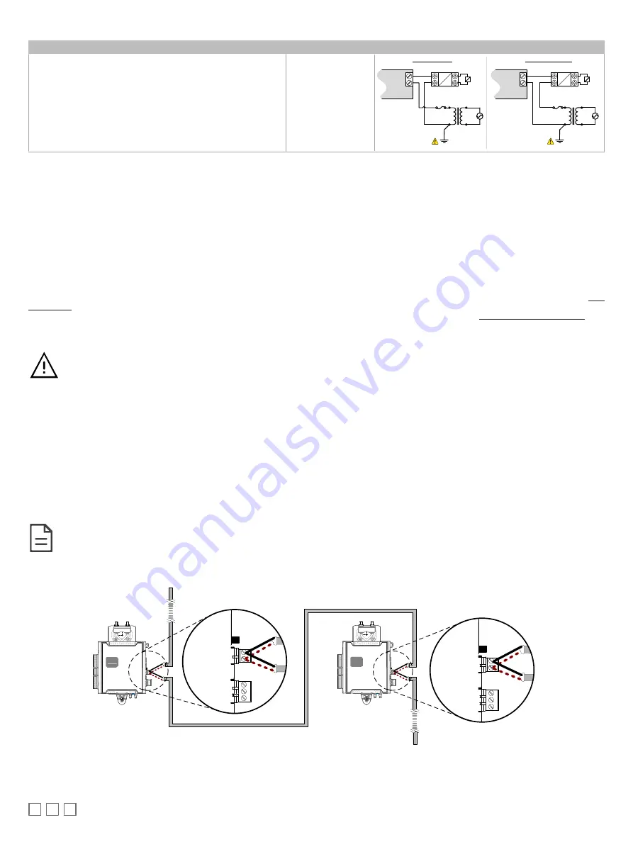
Output Designation
Output Connection Diagram
£
24VAC externally-powered triac output controlling a relay
1
with
line and neutral switching.
£
Ensure that the transformer’s secondary winding is grounded
as shown.
DOx
DOx
Cx
24VAC Relay
A2
A1
Transformer
AC
Electrical
System Ground
Fuse: 4A Max.
Fast Acting
24VAC
Load
DOx
Cx
24VAC Relay
A2
A1
Transformer
AC
Electrical System
Ground
Fuse: 4A Max.
Fast Acting
24VAC
Load
Line Switching
Neutral Switching
Table 4: Output Wiring
1.
Maximum output current for all digital triac outputs is 0.5A continuous or 1A @ 15% duty cycle for a 10-minute period.
Subnet-Wiring
The subnet is used to connect a range of Allure Series Communicating Sensors:
£
The Allure EC-Smart-Vue Series sensor is a communicating room temperature sensor with backlit display graphical menus and VAV balancing ca-
pabilities.
£
The Allure EC-Smart-Comfort and Allure EC-Smart-Air Communicating Sensors are a range of communicating room temperature sensors.
Connect the Allure Series to the controller’s Subnet Port with a standard Category 5e Ethernet patch cable fitted with RJ-45 connectors. Refer to the Net-
work Guide for extensive information and requirements for the connection of the Allure Series. It contains information about network topology and length,
cable type, setting the Subnet ID, etc. It can be downloaded from the
www.distech-controls.com
website. See also the Hardware Installation Guide sup-
plied with the Allure Series.
If you make your own patch cable, see the Allure Series Hardware Installation Guide.
Protect the controller’s connector from being pulled on when a cable to the Allure Series is connected. Create a
strain-relief by looping the cable and attaching it to a solid object with a nylon tie so that a tug on the cable will not
pull out the connector on the controller.
Subnet Wiring with the ECL‑600 Series Controller
ECx-400 series IO Extension Modules are connected to the SUBNET– and terminals of the ECL‑600 series controller. The Network Guide
provides extensive information and requirements to implement the subnetwork for the ECx-400 series IO Extension Modules. It contains information
about network length, cable type, controller addressing, etc. It can be downloaded from our website. See also the Hardware Installation Guide supplied
with the ECx-400 series IO Extension Module.
Communications Wiring
The recommended cable type for L
ON
W
ORKS
®
communications is 22AWG (0.65 mm), twisted pair, unshielded. The L
ON
W
ORKS
communication wire is po-
larity insensitive and can be laid out in a bus, star, loop or free topology. For loop topology, polarity is important, special care must be taken when con-
necting the L
ON
W
ORKS
network to avoid short circuit.
It is recommended to use the bus topology network configuration for all L
ON
W
ORKS
communication wiring, as it allows
for easy network troubleshooting.
Connect both wires to the LON+ and LON‑ terminals of the controller. If inserting multiple wires in the terminals, ensure to properly twist wires together
prior to inserting them in the terminal connectors.
2
1
2
LON
1
LON
LON Network
To Next
Controller
2
1
LON
2
1
LON
Figure 11: Communication Wiring
If inserting multiple wires in the terminals, ensure to properly twist wires together prior to inserting them into the terminal connectors.