10(33)
User manual in Original
Dok. ref: User manual 500A-BS Rev. C
DISPERATOR AB
Tel: +46 8 724 0160
E-mail: [email protected]
Mälarvägen 9, SE-141 71 Segeltorp, Sweden Fax: +46 8 724 6070
Web page: www.disperator.se
3.2.
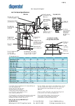
Technical Specification
Technical specification
510A
515A
520A
530A
550A
575A
Normal capacity, kg/hr.
300
400
500
700
850
1000
Electrical power, kW
0,75
1,1
1,5
2,2
4,0
5,5
Rated current, A for:
400V / 3 ph. / 50 Hz
2,1
2,6
3,6
5,2
8,6
11,5
440V / 3 ph. / 60 Hz
2,1
2,4
3,5
5,0
7,5
10,0
480V / 3 ph. / 60 Hz
1,9
2,6
3,5
4,6
7,2
9,6
Other 3-ph voltages available 1-ph 220-240V, 50/60Hz also available for models 510 and 515.
Control voltage
For marine installation the same as motor voltage. For land installation 230V/50Hz.
Fuse rating, slow
10A
10A
10A
16A
16A
16A
Gross / net weight, kg
30 / 26
31 / 27
36 / 32
49 / 45
52 / 48
58 / 54
Measurement a
151
151
151
176
176
176
Measurement b
460 see (3)
460 see(3)
583
560 see (4)
560 see (4)
655
Measurement c
See (3)
See (3)
583-763
560-740 see (4)
560-740 see (4)
655-835
Measurement d
40
40
40
75
75
75
Measurement e
2”
BSP,
Female
2 ½”
BSP,
Female
Measurement f
253
253
253
310
310
310
Measurement g (legs)
See (3)
See (3)
204
236
236
236
The Disposer works in the temperature range -5°C - +40°C
(1) Installation material needed but not incl. in standard delivery are:
• main electrical safety switch,
• flexible hose R½” for cold flush water,
• backflow preventer for flush water,
• water trap for connection to disperator outlet,
• torque protection bar for fixating the disposer.
Can be ordered from DISPERATOR.
(2) For connection to start/stop unit including contactor and overload
protector (IP66) placed on wall/bulkhead. Start/stop unit to be
connected to main electrical safety switch, see (1).
(3) 3-ph unit without legs as standard. Legs available as option and then
with same measurement b, c and g as for model 520. 1-ph unit with
legs as standard and with same measurement b, c and g as for
model 520.
(4) Short version (b = 525 mm and c = 525-705 mm) and long version
(b = 655 mm and c = 655-835 mm) available as option.
(5) User manual with installation and service instructions,
wiring diagram, laminated operating instructions and
laminated safety instructions included in delivery.
d
c b
900
A
min 30
35-40
A
min 300
e
f
g
a
Side view
Top view (A-A)
Disposer outlet to be
connected to a water trap,
see (1). Slope of drain
pipe 2:100 to 5:100
Adjustable legs 3 pcs. for model
520, 530, 550 and 575. Optional
for model 510 and 515, see (3)
Disposer housing,
stainless steel
EN 1.4301 (AISI304)
Air inlet in bottom plate
for motor cooling,
min 15mm clearance
All measurements in mm
Motor IP55
(see table)
To suit drain
connection disposer
with outlet can
be turned and
positioned in any
direction
Torque protection
bar, see (1)
Flush pipe with air gap to sink,
1/2” BSP, Male (optional)
Removable food
waste feeder and
cutlery trap
Assembly for welding
a flange below sink outlet
Welding seam
under sink
Disposer inlet
diam. 80mm
Flushing nozzle for clamp
connection of hose, ½”
BS-nipple
3” BSP, Male
BS-flange 3”
BSP, Female
Back-flow preventer
(vacuum valve), ½”BSP,
Male, see (1)
Reinforced flexible
hose ½” for flushing
water, see (1)
Line strainer,
½” BSP, Female
Solenoid valve, IP65, ½”
BSP, Female, see (2)
Motor cable outlet
and 2 m cable, see (2)
Disposer hood


