background image

5

© 2011 Directed Electronics. All rights reserved.
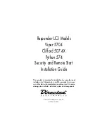
Wiring Diagram

Status LED

Control button

Menu

Wheel

Menu

Wheel

Menu

Wheel

          Control Center 6711T

Note:

 Sensor ports 1 and 2 cannot support sensor 508D due to current limitations. These ports are also 

constant power and ground connections.

5x04

Neutral Safety

Switch

1

10

9

8

7

6
1

2

3

4

5

1

1

8

5

1

1

3

10

12

18

10

9

1

1

12

D2D Port (for external 

Xpresskit interface module)

ON

IMPORTANT! Neutral Safety

switch must be plugged in

and in the ON position

RF Port
for IVU

Control Center

Thermistor/Temp Sensor
Sensor 1

Bitwriter/SmartStart Port

Door Lock

 Port

Remote Start

10-pin Harness

Main 6-pin

 Harness

10A FUSE 

MINI ATM 

RPN: 8540

LIGHT FLASH POLARITY 

(10A (MAXIMUM) FUSE JUMPER)     

Sensor 2

Aux/Shutdown/Trigger 24-pin Harness

Содержание Clifford 507.4X

Страница 1: ...ation Guide This product is intended for installation by a professional installer only Attempts to install this product by a per son other than a trained professional may result in severe damage to a...

Страница 2: ...more information Bitwriter Code Hopping Doubleguard ESP Fail Safe Ghost Switch Learn Routine Nite Lite Nuisance Prevention Circuitry Revenger Silent Mode Soft Chirp Stinger Valet Vehicle Recovery Sys...

Страница 3: ...puts 7 Learning the Tach not needed with Virtual Tach 8 Neutral safety switch interface 8 Testing the neutral safety switch 8 Remote Start Shutdown Startup Diagnostics 9 Remote Pairing 10 Programming...

Страница 4: ...the keys in the ignition The user is responsible for having the neutral safety feature of the vehicle periodically checked wherein the vehicle must not remotely start while the car is in gear This te...

Страница 5: ...s 5x04 Neutral Safety Switch 1 10 9 8 7 6 1 2 3 4 5 1 1 8 5 1 1 3 10 12 18 10 9 1 1 12 D2D Port for external Xpresskit interface module ON IMPORTANT Neutral Safety switch must be plugged in and in the...

Страница 6: ...VISION OUTPUT H2 8 BROWN BLACK 200mA HORN HONK OUTPUT H2 9 DARK BLUE 200mA STATUS OUTPUT H2 10 PINK 200mA IGNITION 1 OUTPUT H2 11 WHITE BLACK 200mA AUX 3 OUTPUT H2 12 VIOLET DOOR TRIGGER INPUT H2 13 W...

Страница 7: ...e for increased sensitivity or Turn it counterclockwise for decreased sensitivity Note You can test the new setting by cautiously impacting the vehicle with increasing intensity while not ing the LED...

Страница 8: ...witch that physically interrupts the starter wire and is used when the vehicle is in any drive gear If the remote start is interfaced before this switch it will provide protection from starting in gea...

Страница 9: ...n in the following table Status LED Flashes Shutdown Mode 1 flash Runtime expired 2 flashes Over rev shutdown 3 flashes Low or no RPM 4 flashes Transmitter shutdown or optional push button 5 flashes B...

Страница 10: ...s displayed 3 Press and release the AUX button until Pair text is displayed 4 Press and hold the AUX button until tones are played on the LC3 remote 5 Successful or Failed Pair The LC3 remote control...

Страница 11: ...only two options AUX option 1 while AUX option 2 For features with more than two options AUX selects the options in ascending order while AUX selects them in descending order Note Pressing AUX button...

Страница 12: ...ensor Full trigger Single Double 13 Door Switch Type Normally open Normally closed 14 Trunk Switch Type Normally open Normally closed 15 Remote Button unlock Ign off On Off 1 System Arming mode 1 Acti...

Страница 13: ...osure Comfort Closure is defeated when arming 2 Comfort Closure 1 the door lock pulse or 2nd pulse for double pulses will remain on for 20 sec onds 3 Comfort Closure 2 800 ms following the end of the...

Страница 14: ...o Remote Start Off 15 Aux 4 Output Type Validity Latch Latch reset ign 30 sec Timed Off 5 2nd Unlock 6 16 Aux 4 Linking No linking Link to Arm Link to Disarm Link to Arm Disarm Link to Remote Start On...

Страница 15: ...ived the wire will turn on for the programmed time duration default 30sec 5 Off the output will not activate for a remote control command use this option when the Aux com mand controls an external dev...

Страница 16: ...tic uses any of the Engine Checking Modes and does not require any special procedures when parking 2 Engine Checking Mode 1 VirtualTach battery voltage drop rise during cranking determines when the st...

Страница 17: ...de activate after they turn off during remote start 2 Latch rear defogger the output activates 10 seconds after start if the interior temperature is below 55 F It turns off after 10 minutes or upon re...

Страница 18: ...Latched 6 Aux 2 Timed Output 30 sec Options 1 to 90 sec 7 Aux 2 Icon Type Pulsed Trunk Window Sunroof Audio Lights Left dr Right dr Rear Hatch Timed Latched 8 Aux 3 Timed Output 30 sec Options 1 to 90...

Страница 19: ...the duration of runtime when the engine is started by the Timer Mode and Smart Start features 13 Timer mode Starts sets the number of times the engine will be started by the Timer Mode and Smart Star...

Страница 20: ...ing Step 4 Virtual Tach Reset Deletes all previously learned values for Virtual Tach and on the next remote start sequence the unit begins virtual tach initialization Note The Zap feature on the Bitwr...

Страница 21: ...not immediately trigger full alarm Instead chirps are heard for the first 3 seconds That s how the progressive two stage door input works This is a feature of this system even if the door is instantl...

Страница 22: ...vehicle to crank 7 If this is a manual transmission vehicle the clutch will need to be bypassed see tech tip 10000 at www directechs com 8 Make sure the purple starter wire is connected on the starte...

Страница 23: ...system Is the door input connected The system needs to see a door open then close after initiating the re mote start Does the vehicle have a delayed dome light If you are connected to the dome light w...

Отзывы: