Dipl.-Ing. H. Horstmann GmbH
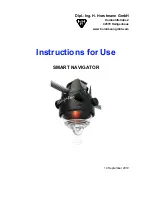
Instructions for Use
2
SMART
NAVIGATOR
C
ONTENTS
Compliance Statements .......................................................................................................................... 4
Regulatory Information for the United States of America .................................................................... 4
Regulatory Information for Canada ..................................................................................................... 4
Regulatory Information for Europe ...................................................................................................... 4
Part 1 - Introduction ................................................................................................................................. 5
1.1 Introduction .................................................................................................................................... 5
1.2 Abbreviations ................................................................................................................................. 5
1.3 Intended use .................................................................................................................................. 5
1.4 Product Overview .......................................................................................................................... 6
Part 2 - Functionality ................................................................................................................................ 7
2.1. Device Description ........................................................................................................................ 7
2.2. fault detection, indication and reset .............................................................................................. 8
2.2.1 Fault Detection .......................................................................................................................... 8
2.2.2 Fault Indication and Reset......................................................................................................... 8
2.2.3 Fault Indication and Line Monitoring by Radio Signal ............................................................... 9
2.3. Wireless Communication .............................................................................................................. 9
2.3.1 Priority Events communicate by exception ............................................................................... 9
2.3.2 Reports communicate by routine interval .................................................................................. 9
2.4. TEST/RESET Contacts .............................................................................................................. 10
2.4.1 Test & Reset Magnet ............................................................................................................... 10
2.4.2 Test & Reset Magnet allocated functions ................................................................................ 10
2.5. Energy Supply ............................................................................................................................ 11
Part 3 - Installation & Operation ............................................................................................................ 12
3.1. Safety Instructions ...................................................................................................................... 12
3.2. Mechanical Installation ............................................................................................................... 12
3.3. SMART NAVIGATOR - operation ............................................................................................. 13
3.3.1 Priority events = report by exception ....................................................................................... 13
3.3.2 Other events ............................................................................................................................ 13
3.3.3 Analog data ............................................................................................................................. 13
3.5 SMART NAVIGATOR @Smart receiver Registration Procedure ............................................... 14
Part 4 - Technical Data .......................................................................................................................... 15
4.1. Product Foto & Label Information ............................................................................................... 16


