background image


The direct path to safe automation


DIN EN 62061, SIL CL 3 

Two-Hand-Control  

according to EN 574: Type IIIC. 


(BG-Nr: ET 06146) 


IND.CONT.EQ

1 Z D 7


MTTF

D

: 25 years 


DC

awg

 99% 


CCF according to EN 62061: 2005 

85 points 

CCF according to ISO 13849-1: 2006  95 points 


PFH

D

 = 6,24x10

-8 


The total concept of the specified category must  
be validated involving the whole control unit.  
 

Variants management 

FW 

DESIGNER  

V404.02x 

V404.03x 

V1.13 


V1.20 

Customer-specific  


V1.31 


V1.32 

Customer-specific 


V1.38 


SafeLine DESIGNER Version 1.38B5


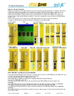
SafeLine modules 

Central module DNSL-ZM 

6 safe digital inputs 
4 safe positive switching outputs 
2 positive switching outputs, free configurable 
1 positive switching output, system ready 
V24 interface 


Central module DNSL-ZMB 

16 safe digital inputs 
2 safe positive switching outputs 
1 relay output with 2 safe contacts 
1 positive switching output, system ready 
V24 interface  
Dual motion and standstill monitoring 


Central module DNSL-ZMT 

11 safe digital inputs 
5 safe analogue inputs 
2 safe positive switching outputs 
1 relay output with 2 safe contacts 
1 positive switching output, system ready 
V24 interface  
Dual motion and standstill monitoring 


Central module DNSL-ZMR 

16 safe digital inputs 
4 safe positive switching outputs 
2 positive switching outputs, free configurable 
1 positive switching output, system ready 
   Control for the relay outputs module DNSL-KM 
V24 interface  
Dual motion and standstill monitoring 


Central module DNSL-ZMK 

6 safe digital inputs 
2 safe positive switching outputs 
1 relay output with 2 safe contacts 
1 positive switching output, system ready 
V24 interface  


Central module DNSL-ZMA 

6 safe digital inputs 
1 analogue input 
2 safe positive switching outputs 
1 positive switching output, system ready 
V24 interface  


Function modules 

Dual standstill, motion and direction monitor 
module DNSL-DS, DNSL-DR 

8 digital inputs 
2 Encoder inputs 
4 positive switching semiconductor outputs 
DNSL-DR only outputs 


Input module DNSL-IN 

16 digital inputs 
4 positive switching semiconductor outputs 


Input / output module 

8 digital inputs 
10 positive switching semiconductor outputs 


Relay module DNSL-RM, DNSL-RM 230 

4 relay outputs  
8 NO contacts 
2 NC contacts only with DNSL-RM 


Relay module DNSL-KM 

4 safe relay outputs every with 2 safe NO contacts 
4 signal contacts 


Field busses


Profibus DP DNSL-DP 

Interface, 24 byte input and output data,  
for diagnostic purpose only 


Ether CAT DNSL-EC 

Interface, 24 byte input and output data,  
for diagnostic purpose only


Содержание SafeLine DNSL-ZM

Страница 1: ...SafeLine Product information Safety for men and machines...

Страница 2: ...mbH Esslinger Stra e 84 72649 Wolfschlugen Tel 07022 95 17 0 Fax 07022 95 17 51 www dinaelektronik de info dinaelektronik de Quality management system DQS certificated according to DIN EN ISO 9001 200...

Страница 3: ...d standstill monitoring Central module DNSL ZMR 16 safe digital inputs 4 safe positive switching outputs 2 positive switching outputs free configurable 1 positive switching output system ready Control...

Страница 4: ...al functions 21 Parameter mask DNCO Function with Teach function 21 Central modules Software elements 22 SafeLine settings Password setting SafeLine diagnostic 23 DNSL DS and DNSL DR Standstill motion...

Страница 5: ...parts of the electronic switchgear carry high voltage DANGER During operation the protective covers must not be removed from the electronic switchgear The device must always be replaced after the firs...

Страница 6: ...on modules DNSL ZMR Rack DNSL DS DNSL DP DNSL IN DNSL IO DNSL RM DNSL KM Central modules Function modules DNSL ZMB DP DNSL ZMT DNSL ZM DNSL ZMA DNSL ZMK DNSL DR DNSL RM 230 DNSL ZMB ZMT and ZMR option...

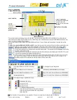
Страница 7: ...le Click the downward arrow button with the left mouse button The variants will be displayed Select the wished variant with a click After a selection of a variant of central module an other window wil...

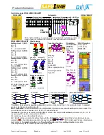
Страница 8: ...ers ZW Anzug selection 3 or 6 on delayed timers Timers Stepping 100ms time domain 100ms to 999 9s 10ms time domain 10ms to 99 9s Off delayed on delayed Fields left Entry of time value 10 1s with selec...

Страница 9: ...ef Reference volt age 15V produced in SafeLine Fields to enter the voltage value Trigger points at ZMT Tension values at ZMA 3 layer Wiring layer Graphic to lift side language Button to select the mod...

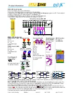
Страница 10: ...Permission function Q E2 E1 Quit E2 E1 manually automatic Two hand function Q1 E1 Q2 E2 only by E1 I1 Q1 I2 E2 I3 Q2 I4 control ZH1 Static input signal only According EN 574 Type IIIC Operation mode S...

Страница 11: ...he outputs O1 O7 is from the A1 input clamp Note All semiconductor outputs will be monitored constantly for wrong behaviour independent of the function If an error is detected on one of the outputs al...

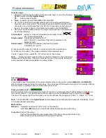
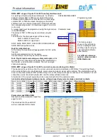
Страница 12: ...ntered and the button will be activated For every frequency table the encoder input at motion monitoring equipment has to be defined The selection has to be done vie Encoder1 2 DS to Teach For this fu...

Страница 13: ...by E1 I1 Q1 I2 E2 I3 Q2 I4 control ZH1 Static input signal only According EN 574 Type IIIC Operation mode Switch BAWS One from three 24V DC BA Mode 1 2 3 I1 to I3 One from six 24V DC BA Mode 2 3 4 5 6...

Страница 14: ...in the parameter layer to function as a one channel not safe motion control As impulse device a proximity switch may be used Setting the value for the motion control will be done using the PROFIBUS Th...

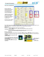
Страница 15: ...l Function modules There is no single channel processing SAFELINE DESIGNER Parameter mask Programming mask The tension values shown in the left picture are for a safety mat with shorting outputs using...

Страница 16: ...s Behavior Output O1 switched off LED for O1 not illuminated Left LED at ZMB block not on Right LED at block blinking sequence short long Correction Check the wiring Check the configuration wrong asse...

Страница 17: ...activated directly by external inputs or by virtual connections from NC NO logic elements time relays etc O6 O7 Clock output supply for cross circuiting detection in safety circuits E1 E2 No virtual...

Страница 18: ...DNSL PR Programming device for user application The user application data can be transfer to the memory card via the programming device DNSL PR DNSL PR is deliverable with all necessary connection cab...

Страница 19: ...at position 4 of the rack Four safety outputs each consisting of 4 safety contacts and 2 signaling contacts are available then Position 2 in the rack is reserved for the field bus module Parameter ma...

Страница 20: ...nnection scheme 14 V24 COM PORT Netzteil Power supply 24V DC I1 I2 I3 I4 I5 O1 O2 O3 13 23 24 A2 A1 0V 24V intern 6A I6 Eing nge Inputs Ausg nge Outputs UB 24V DC Wiring layer Inputs usage Look at DNS...

Страница 21: ...ged These values is used for the cross circuiting detection There for the used voltage range is only from 10 to 90 DNCO function with Teach function This function enables the monitoring of the circumf...

Страница 22: ...AND X6 inverted XOR Y7 X7 AND X8 Y8 Start Stop Start X7 Stop X8 default stop The reset status is Y8 0 X7 Set und X8 Set Y8 0 Logic module 15 x LM type 2 Y1 not X1 Y2 AND X1 X8 8 Input AND Y3 OR X1 X8...

Страница 23: ...ly for initial loading COM1 Selection of the serial Port used on the PC If an USB V24 converter is used the COM interface will only be available if the converter is operational Password setting Withou...

Страница 24: ...errors can be detected this way The programmed and actual frequency values of the moni tored motions will be displayed The adjusted Soll and ac tual Ist frequencies of the motion control module will b...

Страница 25: ...onal functions Emergency Off E1 E2 E1 E2 Q Quit manually automatic Protection cover function E1 E2 11 12 21 22 E1 E2 Q 11 12 21 22 13 14 23 24 automatic Permission function Q E2 E1 Quit E2 E1 manually...

Страница 26: ...nt speed and speedup The outputs are changing to HIGH signal if the speed decrease about 5 at the latest of 500ms The shortest reaction time is 100ms The virtual outputs BR1 and BR2 can control hardwa...

Страница 27: ...ssible using 2 DNCO1 units 2 4 Inputs B11 B14 and B21 B24 select 16 values each from the table using 2 DNCO1 units 3 6 Inputs B11 B14 B21 and B22 select 48 values from the table An independent usage f...

Страница 28: ...B21 B24 Digital Selection of one maximal speed in the automatic function mode Freq Tabelle 1 DZ 2 DZ Selection a frequency table for different maximal speed in the automatic function mode Selection of...

Страница 29: ...on Q1 E1 Q2 E2 only by E1 I11 Q1 I12 E2 I13 and Q2 I14 control ZH1 Static input signal only according EN 574 Type IIIC Programming Layer manually Q E1 E2 SK1S SK4S SK1 SK4 automatic E1 E2 SK1S SK4S SK...

Страница 30: ...he wiring layer if the function single output is selected in the parameter mask A mixed usage is possible Note All outputs will be monitored constantly for wrong behavior independent of the func tion...

Страница 31: ...input signal only according EN 574 Type IIIC Wiring Layer manually Q E1 E2 SK1S SK4S SK1 SK4 automatic E1 E2 SK1S SK4S SK1 SK4 Safety cover function Q E1 E2 SK1 2 Two hand function Q2 E1 E2 ZH1 Q1 500...

Страница 32: ...layer if the function single output is selected in the parameter mask Setting of O21 O22 Clock output supply for cross circuiting detection in safety circuits E1 E2 No virtual wiring possible Paired...

Страница 33: ...cuit via static or clock signal cross circuiting detection O11 O12 O13 O14 O15 O16 O17 O18 Selection of the outputs function as follows 1 channel safe redundant outputs parallel switched 1 channel ant...

Страница 34: ...fety category 4 REL11 REL12 controlled by S1 REL21 REL22 controlled by S2 The virtual clamps S1 S2 are displayed in the wiring layer only if the function paired output is selected in the parameter mas...

Страница 35: ...t activited in the mask Ignore encoder signal Spindle deactivation look down Dynamic data update The data will be updated immediately Update The data will be updated every 100ms respectively every 25m...

Страница 36: ...s to the PLC The data will be transferred via the input byte EB8 The PLC has to reconfirm the equal spindle ID number during 2s via the output byte AB8 If the ID numbers are not equal the spindle will...

Страница 37: ...ween a master category 1 and the slave A field BUS communication loss will not disturb the safety function of SafeLine Only the output buffer will be cleared An internal communication loss between the...

Страница 38: ...entral module cover DNSL R2 58 Central module FB DNSL R2 58 Central module 1 module DNSL R3 81 Central module FB 1 FM DNSL R3 81 Central module 2 modules DNSL R5 125 Central module FB 3 FM DNSL R5 125...

Страница 39: ...ng semiconductor output Residual current at output short circuit to A2 0V 5 A Residual voltage at 1A load 200mV Residual voltage at 0 5A load 100mV Residual voltage at minimum load 0 1A 50mV Minimum c...

Страница 40: ...es Short circuit strength 1000A SCPD 6A gG safety fuse Maximum switching rate 360 cycles h with max current DC13 Typical reaction time Typical drop out time 10ms Potentiometer connection for DNCO Func...

Страница 41: ...witching and continuous current for all outputs Max 2A DNSL IN technical data Power consumption at A1 A2 via the central module Max 1 7W Technical data of outputs O11 O12 O21 and O22 Switching and con...

Страница 42: ...ching cycles Electrical product life AC15 3A 230V 80000 switching cycles Mechanical product life 10 x 10 6 switching cycles Contact fusing 5A slow Maximum switching cycles 360 cycles h with max curren...

Страница 43: ...Product information Products safety technology SafeLine redaction 11 date 10 04 09 page 43 from 48...

Страница 44: ...t error date Solution Date has to have the following format dd mm yyyy This adjustment must be done in the Windows system control Wiring Error A second wire will be con nected to a wired virtual conne...

Страница 45: ...Hz Handling errors Problem Online diagnostic without a downloaded project Solution Please download a project from PC or SafeLine Problem No print option is selected Solution Please select a print opti...

Страница 46: ...Product information Products safety technology SafeLine redaction 11 date 10 04 09 page 46 from 48 Certificate...

Страница 47: ...Product information Products safety technology SafeLine redaction 11 date 10 04 09 page 47 from 48...

Страница 48: ......

Отзывы: