Product information
Products: safety technology
SafeLine
redaction 11 date 10.04.09 page 11 from 48
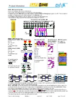
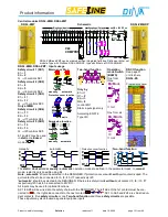
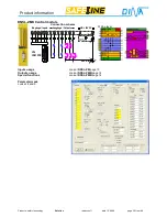
Outputs usage
1. Output O1 function may be defined in the parameter layer to one of the following:
SLOK
: Output indicating
System Ready
T8
:
Semi conductor switch
2.
FrqIn
: possible only with DNSL-ZMB, ZMT and ZMR
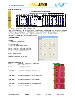
3. O2, O3, O4 and O5 are redundant outputs made of a positive switching semi-
conductor and a relay contact. These outputs may be activated directly by exter-
nal inputs or by virtual connections from NC, NO, Logic-elements, time delay re-
lays etc. The wiring is done by the virtual control inputs in the DESIGNER.
4. O6 and O7 are free usable outputs. The usage may be defined in the parameter
layer to the following:
Clock output
supply for cross-circuiting detection in safety circuits,
E1
E2
No virtual wiring possible
Single outputs
individually activated by T6, T7
Note: T6 and T7 only visible, if this mode is selected in the
parameter layer.
Paired output
Safe output to duplicate dual channel contacts.
Activated by S1 and Q
Q may be wired to virtual 24V directly or can be used from an external input.
S1 and Q are only visible, if this mode is selected in the parameter layer.
The 24 V supply for the outputs O1 – O7 is from the A1 input clamp.
Note:
All semiconductor outputs will be monitored constantly for wrong behaviour
independent of the function. If an error is detected on one of the outputs, all outputs
will be switched off after an adjustable time delay (0-25s).
Wiring layer
Special functions
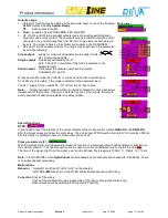
RTDS
Virtual input to reset the interlock of the virtual contacts of the motion control module
DNSL-DS
, and
DNSL-DR
after the actual values are below the limit values. The virtual input RTDS must be held at 24V for more then 500ms.
For this function a hardware input or virtual output can be used.
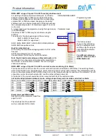
Pulse generator via IF1
With the selection „ON” via the parameter mask the function of a pulse generator (Takt Generator) is possible via
the virtual contact IF1. The right connection can be used to control an hardware output, the left to virtual
The time of the signal „High“ and the signal „Low“ can be defined. The stepping is 100ms. 1 = 100ms, 10 = 1s etc.
Note:
in the SAFELINE
unit all
digital inputs
are processed by both channels and checked for Plausibility. There
is no single channel processing.
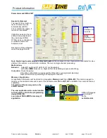
Malfunctions
Behavior
: Output O1 switched off. LED- for O1 not illuminated.
Left LED at
ZM
Block not on. Right LED at Block blinks sequence short/long.
Correction
: Check of the wiring
Check of the configuration (wrong assembly of the rack or wrong project planning.)
Reset stored errors by switching 24V supply OFF and ON.
Содержание SafeLine DNSL-ZM
Страница 1: ...SafeLine Product information Safety for men and machines...
Страница 43: ...Product information Products safety technology SafeLine redaction 11 date 10 04 09 page 43 from 48...
Страница 46: ...Product information Products safety technology SafeLine redaction 11 date 10 04 09 page 46 from 48 Certificate...
Страница 47: ...Product information Products safety technology SafeLine redaction 11 date 10 04 09 page 47 from 48...
Страница 48: ......


