background image

EN-2

452114.66.73 · FD 9306

Smart-RTC

English

1 Please read immediately

1.1 Important information

ATTENTION!

During start-up, observe the respective national safety regulations and
the applicable VDE safety regulations, particularly VDE0100, as well as
the technical connection requirements of the utility company (EVU) and
network operator!

ATTENTION!

This device must only be opened and installed by a certified electrician
according to the corresponding circuit diagram in the casing cover / on
the casing / in the operating instructions. The relevant safety regulations
must be observed. Caution! Operation close to devices which do not
comply with the EMC guidelines can interfere with the functioning of the
device. After installation, the specialist carrying out the installation must
instruct the operator in the functioning and operation of the regulation.
The operating instructions must be kept in a location which is freely
accessible for the operating and service personnel.

ATTENTION!

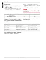
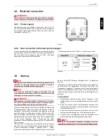
Only one Smart-RTC must be connected per heat pump manager. A
screened cable of 2 x 0.25mm

²

 must be used.

ATTENTION!

If a Smart-RTC is used, no other device must be 
connected to the RS 485 interface (field card).

ATTENTION!

To ensure that the frost protection function works properly, the heat
pump manager and the extension modules must remain connected to the
power supply at all times.

ATTENTION!

Extra-low voltage is applied at terminals Rx + / Tx+ / Rx-  / Tx- and GND of
the Smart-RTC. Line voltage (230 V

~

) at these terminals destroys the

electronic components of the controller

ATTENTION!

Room temperature regulation with Smart-RTC is possible from heat pump
manager software version L01 and Bios version 5.08 onwards.

ATTENTION!

Work must only be carried out by qualified personnel. Before carrying out
any work, always ensure that there is no voltage present at the terminals.

ATTENTION!

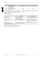
If communication cannot be established, the address set on the Smart-
RTC must be checked. WPM software version L03 requires Address 1;
from version L04 Address 50 must be set on the Smart-RTC.

1.2 Intended use 

This device is only intended for use as specified by the
manufacturer.  Any other use beyond that intended by the
manufacturer is prohibited. This requires the user to abide by the

manufacturer's product information. .Tampering with or altering
the device is not permitted

1.3 Legal regulations and directives

Construction and design fulfil all valid EU directives, DIN and
VDE regulations.
When connecting the room temperature controller to the power
supply, the relevant VDE, EN and IEC standards must be
fulfilled. 
Persons, especially children, who are not capable of operating
the device safely due to their physical, sensory or mental abilities

or due to their inexperience or lack of knowledge, must not
operate this device without supervision or instruction by the
person in charge. 
Children must be supervised to ensure that they do not play with
the device. 

The connection requirements described in these
instructions must be observed. 

2 General

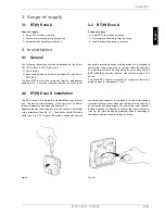
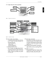
In combination with the heat pump manager, the Smart-RTC
(room temperature controller) controls the room temperature of a
reference room by adjusting the return temperature. The
temperature sensor is integrated into the device. The heating
circuit of the reference room must not be closed off with a valve.
For the cooling operating mode in the heat pump, the Smart-RTC
with humidity sensor must be used. The cooling function is
interrupted by the Smart-RTC if the dew point is not reached. The
Smart-RTC is available in a surface-mounted (RT(H) Econ A)
and a flush-mounted version (RT(H) Econ U).

Содержание RT Econ A

Страница 1: ...perating Instructions Instructions d installation et d utilisation Raumtemperatur Regler zum Anschluss an den W rmepumpen manager RTHmit Feuchtef hler Room temperature controller for connection to the...

Страница 2: ......

Страница 3: ...U DE 3 3 2 RT H Econ A DE 3 4 Montage DE 3 4 1 Allgemein DE 3 4 2 Montage RT H Econ U DE 3 4 3 Montage RT H Econ A DE 4 4 4 Elektrischer Anschluss DE 5 4 4 1Stromversorgung DE 5 4 4 2Busverbindung zu...

Страница 4: ...elektrischen Anschlussarbeiten auf Span nungsfreiheit pr fen ACHTUNG Kann keine Kommunikation hergestellt werden so muss am Smart RTC die eingestellte Adresse kontrolliert werden Die W rmepumpenmanage...

Страница 5: ...kann Auch kann der Betrieb in der N he von Ger ten die nicht den EMV Richtlinien entsprechen zur Beeinflussung der Ger tefunktion f hren Die Montage des Smart RTC sollte in einer H he erfolgen in der...

Страница 6: ...lussteil A1 links oder rechts neben dem Display befestigt wird Um die richtige Einbaulage f r das Display zu erhalten muss die Schraube A3 gel st werden Jetzt die Halterung ent sprechend der Einbaulag...

Страница 7: ...werden so muss am Smart RTC die eingestellte Adresse kontrolliert werden Die W rmepumpenmanager Software Version L03 erwartet die Adresse 1 und ab der WPM Software Version L04 muss die Adresse 50 am S...

Страница 8: ...erm glicht es den Heizbetrieb oberhalb einer einstellbaren Au entemperatur zu sperren Fehlerhilfe Bei der Inbetriebnahme ist auch die Montage und Bedienungs anweisung des W rmepumpenmanager zu beacht...

Страница 9: ...ird die am W rmepumpenmana ger eingestellte max R cklauf Temperatur verwendet Ein Balken entspricht der Dauer von 20 min Durch mehrmaliges Dr cken kann die Zeit auf 40 bzw 60 Minu ten erh ht werden F...

Страница 10: ...DE 8 452114 66 73 FD 9306 Deutsch Smart RTC...

Страница 11: ...RT H Econ A EN 3 4 Installation EN 3 4 1 General EN 3 4 2 RT H Econ U installation EN 3 4 3 RT H Econ A installation EN 4 4 4 Electrical connection EN 5 4 4 1 Power supply EN 5 4 4 2 Bus connection t...

Страница 12: ...Work must only be carried out by qualified personnel Before carrying out any work always ensure that there is no voltage present at the terminals ATTENTION If communication cannot be established the...

Страница 13: ...lush type box Operation close to devices which do not comply with the EMC guidelines can also interfere with the functioning of the device The Smart RTC should be installed at a height at which the di...

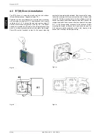
Страница 14: ...ither located to the left or to the right of the display Screw A3 must be loosened in order for the correct mounting position for the display to be obtained After loosening the scerw rotate the mounti...

Страница 15: ...tary pushbutton to change the value and press the button to confirm the new value First the value 22 must be selected and confirmed Following this the required address must be set and confirmed using...

Страница 16: ...all ceiling 22 C 30 C Low temperature radiators 45 38 C 25 C 40 C Radiators 55 45 C 30 C 50 C Measure 1 Measure 2 Building too hot Reduce room set temperature Reduce minimum return temperature Buildin...

Страница 17: ...pump manager is used as the return set temperature One bar indicates a duration of 20 minutes Repeated pressing of the button extends the duration to 40 or 60 minutes Domestic hot water preparation i...

Страница 18: ...EN 8 452114 66 73 FD 9306 Smart RTC English...

Страница 19: ...3 4 Montage FR 3 4 1 G n ralit s FR 3 4 2 Montage du r gulateur RT H Econ U FR 3 4 3 Montage du r gulateur RT H Econ A FR 4 4 4 Branchements lectriques FR 5 4 4 1 Cordon d alimentation lectrique FR 5...

Страница 20: ...sp cialiste lectricien est habilit effectuer les travaux de montage lectrique V rifier l absence de tension avant de commencer les travaux ATTENTION Si aucune communication ne peut tre tablie contr le...

Страница 21: ...eur proximit d appareils lectriques ne r pondant pas aux directives CEM peut influencer son fonctionnement La hauteur de montage du r gulateur Smart RTC doit encore permettre une lecture facile de son...

Страница 22: ...raccordement A1 soit mont e gauche ou droite de l cran Pour obtenir la bonne position de montage de l cran d tacher la vis A3 Faire pivoter alors le support en fonction de la position de montage et l...

Страница 23: ...ant env 3 sec Le texte Code appara t La valeur peut tre modifi e en tournant le s lecteur rotatif poussoir puis confirm e par une pression Il faut d abord s lectionner la valeur 22 et la confirmer Pui...

Страница 24: ...Temp rature de retour maximale Chauffage par surface 35 28 C sol paroi plafond 22 C 30 C Radiateurs basse temp rature 45 38 C 25 C 40 C Radiateurs 55 45 C 30 C 50 C 1 re mesure 2 me mesure B timent t...

Страница 25: ...temp rature retour de consigne prise en compte est la temp rature retour maximum r gl e sur le gestionnaire de pompe chaleur Une barre correspond une dur e de 20 min Une pression r p t e du bouton s l...

Страница 26: ...FR 8 452114 66 73 FD 9306 Smart RTC Fran ais...

Страница 27: ...s Smart RTC Anhang Appendix Annexes 1 Technische Ger teinformationen Technical Device Information Informations techniques sur les appareils A II 2 Abmessung Dimensions Dimensions A III 2 1 RT Econ U R...

Страница 28: ...sistance R sistance la chaleur et au feu Kategorie D Category D Cat gorie D Schutzklasse Ber hrungsschutz Protection class touch protection Classe de protection protection contre les contacts 2 berspa...

Страница 29: ...452114 66 73 FD 9306 A III Anhang Appendix Annexes Smart RTC 2 Abmessung Dimensions Dimensions 2 1 RT Econ U RTH Econ U 2 2 RT Econ A RTH Econ A...

Страница 30: ...A IV 452114 66 73 FD 9306 Anhang Appendix Annexes Smart RTC...

Страница 31: ...452114 66 73 FD 9306 A V Anhang Appendix Annexes Smart RTC...

Страница 32: ...ales service addresses please refer to the Installation and Operating Instructions for Heat Pumps Pour les conditions de garantie et les adresses SAV se r f rer aux instructions de montage et d utilis...

Отзывы: