


5
EXPLODED PARTS DIAGRAM
Replacement Parts List
12
6
1
2
3
4
13
10
11
13
8
14
9
Heater Assembly
1.
. . . . . . . . . . . . . . . . . . 2200490600RP
Glass Assembly
2.
. . . . . . . . . . . . . . . . . . 6904190200RP
Flicker Motor
3.
. . . . . . . . . . . . . . . . . . . . . 2000210300RP
Flicker Assembly
4.
. . . . . . . . . . . . . . . . . 5901070200RP
Cutout
5.
. . . . . . . . . . . . . . . . . . . . . . . . . . 2300270400RP
Cord Set
6.
. . . . . . . . . . . . . . . . . . . . . . . . 4100190100RP
Lampholder Wire Assembly
7.
. . . . . . . . . 2500450100RP
Remote Receiver
8.
. . . . . . . . . . . . . . . . . 3000380200RP
3-Position Switch
9.
. . . . . . . . . . . . . . . . . 2800071100RP
2-Position Switch
10.
. . . . . . . . . . . . . . . . . 2800070200RP
Thermostat
11.
. . . . . . . . . . . . . . . . . . . . . . 2300150100RP
Terminal Block
12.
. . . . . . . . . . . . . . . . . . . . 4000070100RP
Capacitor
13.
. . . . . . . . . . . . . . . . . . . . . . . . 2300030100RP
Remote Control
14.
. . . . . . . . . . . . . . . . . . . 3000370500RP
Control Knob
15.
. . . . . . . . . . . . . . . . . . . . . 8800620100RP
7
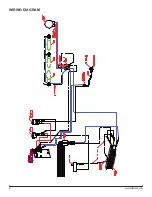
Содержание EWF-SS
Страница 6: ...6 www dimplex com Wiring Diagram...


