Dimplex EWF-SS Скачать руководство пользователя страница 4


www.dimplex.com

MAINTENANCE

  WARNING:  

Disconnect power before attempting any 

maintenance or cleaning to reduce the risk of fire, electric 

shock or damage to persons.

Light Bulb Replacement

Allow at least five (5) minutes for light bulbs to cool before 

touching bulbs to avoid accidental burning of skin.
Light bulbs need to be replaced when you notice a dark 

section of the flame or when the clarity and detail of the log 

exterior disappears.  There are two (2) bulbs under the log 

set which generate the flames and embers.

Helpful Hints: 

It is a good idea to replace all light bulbs 

at one time if they are close to the end of their rated life.  

Group replacement will reduce the number of times you 

need to open the unit to replace light bulbs.

Light Bulb Requirements:

  Quantity of three (3) – 60 Watt 

chandelier or candelabra bulbs with E-12 (small) socket 

base, 120 Volt. 

DO NOT EXCEED 60-WATTS PER BULB.

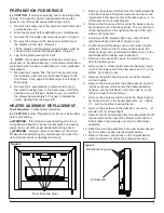
Bulb Replacement Instructions:

Unplug the unit from the outlet.

1. 

Remove glass assembly as shown in Figure 3.

2. 

Reach in and turn the burnt-out bulb(s) (or all bulbs) 

3. 

counter-clockwise to remove.
Replace with new bulbs.

4. 

Fit glass assembly back in place.

5. 

Plug in the Sahara fireplace.

6. 

Glass Cleaning

The front glass is cleaned in the factory during the 

assembly operation.  During shipment, installation, 

handling, etc., the front glass may collect dust particles, 

these can be removed by dusting lightly with a clean dry 

cloth.

To remove fingerprints or other marks, the glass can be 

cleaned with a damp cloth.  The glass should be completely 

dried with a lint free cloth to prevent water spots.  To 

prevent scratching, do not use abrasive cleaners or spray 

liquids on the glass surface.

Sahara Fireplace Surface Cleaning

To remove fingerprints or other marks, the exterior finish 

can be cleaned with a damp cloth with a mild detergent.  

The surface should be completely dried with a lint free cloth 

to prevent water spots.  
To prevent scratching, do not use abrasive cleaners or 

spray liquids on any surface.


1

2

3

Figure 3

Содержание EWF-SS

Страница 1: ...orth America Limited Dimplex North America Limited 1367 Industrial Road Cambridge ON Canada N1R 7G8 1 888 346 7539 www dimplex com REV PCN DATE 00 2 SEP 11 IMPORTANT SAFETY INFORMATION Always read thi...

Страница 2: ...s and techniques which if not carefully followed will expose the user to the risk of fire serious injury or death OPERATION 3 Maintenance 4 Exploded Parts Diagram 5 Wiring Diagram 6 PREPARATION FOR SE...

Страница 3: ...sed of properly Check with your Local Authority or Retailer for recycling advice in your area OPERATION Figure 1 The controls are located on the bottom surface of the Sahara fireplace on the right sid...

Страница 4: ...placement Instructions Unplug the unit from the outlet 1 Remove glass assembly as shown in Figure 3 2 Reach in and turn the burnt out bulb s or all bulbs 3 counter clockwise to remove Replace with new...

Страница 5: ...0RP Flicker Assembly 4 5901070200RP Cutout 5 2300270400RP Cord Set 6 4100190100RP Lampholder Wire Assembly 7 2500450100RP Remote Receiver 8 3000380200RP 3 Position Switch 9 2800071100RP 2 Position Swi...

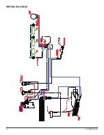
Страница 6: ...6 www dimplex com Wiring Diagram...

Страница 7: ...ock or damage to persons Remove the screws which secure the heater assembly 1 to the back panel 4 Smaller screws secure the mount ing bracket in the lower center of the back panel 2 on left bracket an...

Страница 8: ...the housing below the flicker motor Turn the unit over and lay it on to its front to secure 23 the remaining 6 screws from behind the back panel 4 for the fan housing panel and 2 for the switch housi...

Страница 9: ...s slightly bend the flanges that 15 are holding the wire harness in the channel Bend them just enough to feed the wires out of the channel Remove the 2 screws that are securing the wire har 16 ness to...

Страница 10: ...the switches and bottom closest to you Locate the switch housing cover on the lower interior 2 right side Remove the 2 screws which secure the upper housing cover just below the flame motor to the el...

Страница 11: ...lace on the junc tion box cover and remove the cord Feed the new power cord through the junction box and 8 squeeze the new strain relief in place on the cord and junction box Re connect wires Wide bla...

Страница 12: ...PART PICTURES Light Socket Bracket and Bulbs Light Harness Channel Heat Deflector Grille Flicker Rod and Bracket Thermostat Dial and Control Rear Flame Panel Flicker Rod Heater Assembly and Cover Ligh...

Страница 13: ...ote Receiver Board Heater On Off Switch Black wire from Flicker Motor and Neutral from Remote Receiver Board Switch Output Heater On Off Switch and Terminal Block Capacitor and Brown wire from Flicker...

Страница 14: ...gh Temperature Cutout Line in From Thermostat Line out to Heater Upper Heating Element Connects to Heater Blower Motor and From Terminal Block Heater On Off Switch Main On Off Remote Switch Thermostat...

Страница 15: ...et Check Fuse Breaker Panel Defective Main On Off Remote switch Replace Main On Off Remote switch Defective circuit board Replace circuit board Loose wiring Check wiring connections Fireplace does not...

Страница 16: ...ce thermostat Loose wiring Trace wiring in unit Defective heater assembly Replace heater assembly Heating element is glowing red Normal Operation Small glowing sections of the element are considered n...

Отзывы: