


12
www.dimplex.com
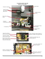
VIEW FROM UPPER LEFT SIDE
(ELECTRICAL/SWITCH HOUSING COVER REMOVED)
VIEW FROM BOTTOM RIGHT SIDE
(ELECTRICAL/SWITCH HOUSING COVER STILL ATTACHED)
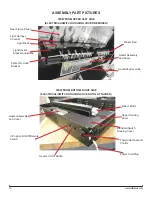
ASSEMBLY PART PICTURES
Light Socket
Bracket and Bulbs
Light Harness
Channel
Heat Deflector Grille
Flicker Rod and
Bracket
Thermostat Dial and
Control
Rear Flame Panel
Flicker Rod
Heater Assembly
and Cover
Light Block
Flicker Motor
3-Position On/Off/Remote
Switch
Heater On/Off Switch
Power Cord/Plug
Electrical/Switch
Housing Cover
Heater Assembly
and Cover
Upper Housing
Cover
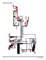
Содержание EWF-SS
Страница 6: ...6 www dimplex com Wiring Diagram...


