© 2022 Digitrax, Inc.
www.digitrax.com
5
5
1.0 Quick Start Guide
These instructions will get you up and running in just a few minutes! It is recom-
mended that you use this quick start guide before adding the to an existing
Digitrax installation to ensure the is configured in working order, and to
observe any features you may be unfamiliar with. Once you’ve completed the initial
review of your on a test bench, you can remove your existing CS from your
layout and replace it with. the . These setup steps are broadly similar to
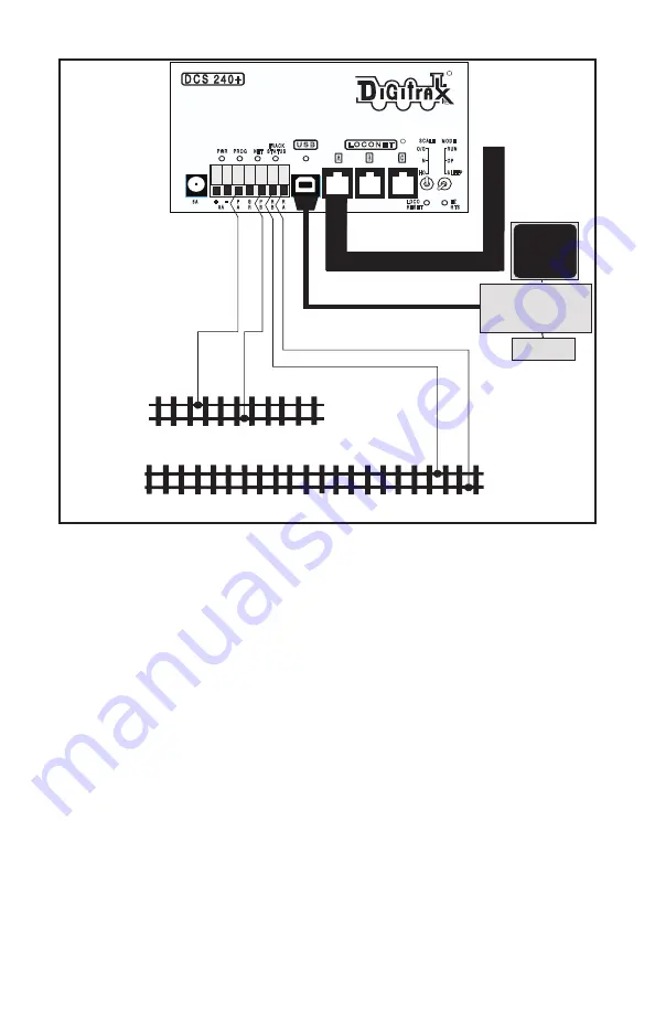
debug steps of a if problems are encountered. Figure 1 shows the
connection and front panel layout.
1.1 Standalone setup and powering:
1. Disconnect the RA/RB and PA/PB leads on the 7-pin layout connect plug. Discon-
nect the 3 LocoNet RJ12 and USB ports. This isolates layout wiring issues.
2. Set the ’s SCALE switch to the scale you are running: N, HO, O/G. Use
the lowest setting and DC input voltage that will run your layout.
3. Set the
MODE
switch on the to the
RUN
position.
4. Connect the 5A capacity DC power supply of 13.8V DC minimum voltage via the
2mm DC jack, or an e.g. 8A/13.8V supply via the 8A+/- terminals.
5. The will beep twice and its PWR indicator will light GREEN, winking
off every 3 seconds as a “Heartbeat”. At first power up the RED PROG led will
flash for about 3 seconds and then go off, showing internal diagnostics are com
-
plete.
6.
NET led will light RED showing LocoNet is active hi, and not held off. The BLUE
PROG A (PA)
RAIL A (RA)
Isolated Programming Track
Main Layout Tracks
PROG B (PB)
RAIL B (RB)
E Z
R T S
R
L O C O N E T
A
B
R
C
U S B
P W R P R O G
N E T
T R A C K
S T A T U S
M O D E
R U N
O P
S L E E P
S C A L E
O / G
N
H O
+
P
A
G
R
P
B
R
B
R
A
5 A
L O C O
R E S E T
-
8 A
MONITOR
KEYBOARD
USB Connector
PC
LocoNet to layout
USB connection to PC
Figure1:
connections


