17
CAUTIONS FOR INSTALLATION AND
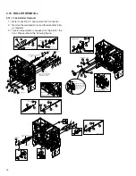
CLEANING OF BOTH ROLLERS
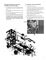
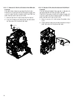
1) The oil bearing
%
is on the tip of the roller assembly.
Do not forget it at the time of installation and re-
moval.
2) When installing a new roller, take care that it will not
hit the bracket.
3) AC 100 V is impressed to this heater. Use sufficient
care for the wire processing.
4) Do not turn the roller by hand. The thermistor may
become damaged when the roller is turned by hand.
Accordingly, when a roller is to be turned for
cleaning etc., do the turning while the bracket
on which the thermistor is installed has been
raised a little.
2.2 REMOVAL OF THE CAM MOTOR
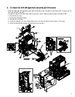
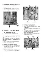
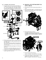
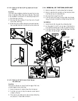
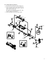
1) Remove the two screws A.
Please use a long screwdriver for the lower screw.
If the power supply unit is in the way, raise it once
and use the gap underneath to perform the work.
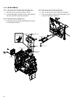
2) Remove the screw B from front side.
Refer to section 2.9 to remove the front panel.
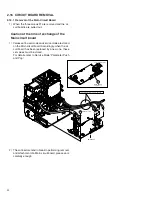
3) Insert the screwdriver to the hole fixing the card cool-
ing fan, and remove another screw B.
(Refer to section 2.14.3)
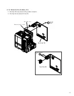
4) Disconnect the flat wire and the other cables.
5) Raise the bend remedial roller and pull out the mo-
tor, taking care that the motor bracket will not hit
circuit boards etc.
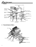
Screw A
Screw B
(Front side)
5
(TSS0189)
3
(TSS0182)
15
Clamp
(T2,H2)
H2
P4
17
17
T1
T2
Clamp
1
15
(TSS0181)
Pass the wires
behind the lever
(-010)
(-010)
17
KJJ46271
-003x2
KJJ46271-003
KJJ46271-003
KJJ46271
-003x2
18
QYSPSPD
4008N
H1
T1
T2
12
Clamp
(P4)
F1
Clamp
(F1)
(FD M.MOTOR ASY)
A
B
Cam motor
Screw A
Retransfer roller
Bend remedial roller
Bearing
Thermistor bracket
screw B
17
KJJ46271
-003x2

