26
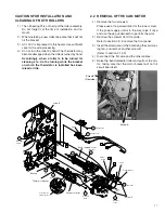
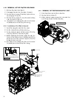
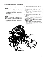
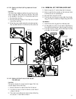
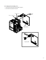
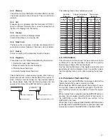
2.12.11 Removal of the Door Interlock Circuit Board
Function
This circuit board detects opening of the front door.
The DC 24 V power put out from the power supply unit
is cut off when the door interlock switch and the cas-
sette interlock switch are not both ON.
1) Refer to section 2.9 and remove the front panel.
2) The door interlock circuit board can be removed af-
ter the screw (15) has been removed.
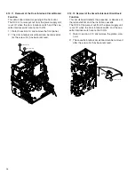
2.12.12 Removal of the Cassette Interlock Circuit Board
Function
This circuit board detects the presence or absence of
the retransfer film and the ink ribbon cassette.
The DC 24 V power put out from the power supply unit
is cut off when the door interlock switch and the cas-
sette interlock switch are not both ON.
1) Refer to section 2.10 and remove the platen sole-
noid.
2) The cassette interlock circuit board can be removed
after the screw (16) has been removed.
KJJ46271-003
Door interlock
RED
15
8
J4
J3
16
KJJ46271-001x2
Cassette
interlock


