background image

2-4

2.4

Inspection after Unpacking

1.

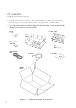
Carefully check the printer and the accessories for visible damage.

2.

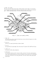
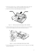
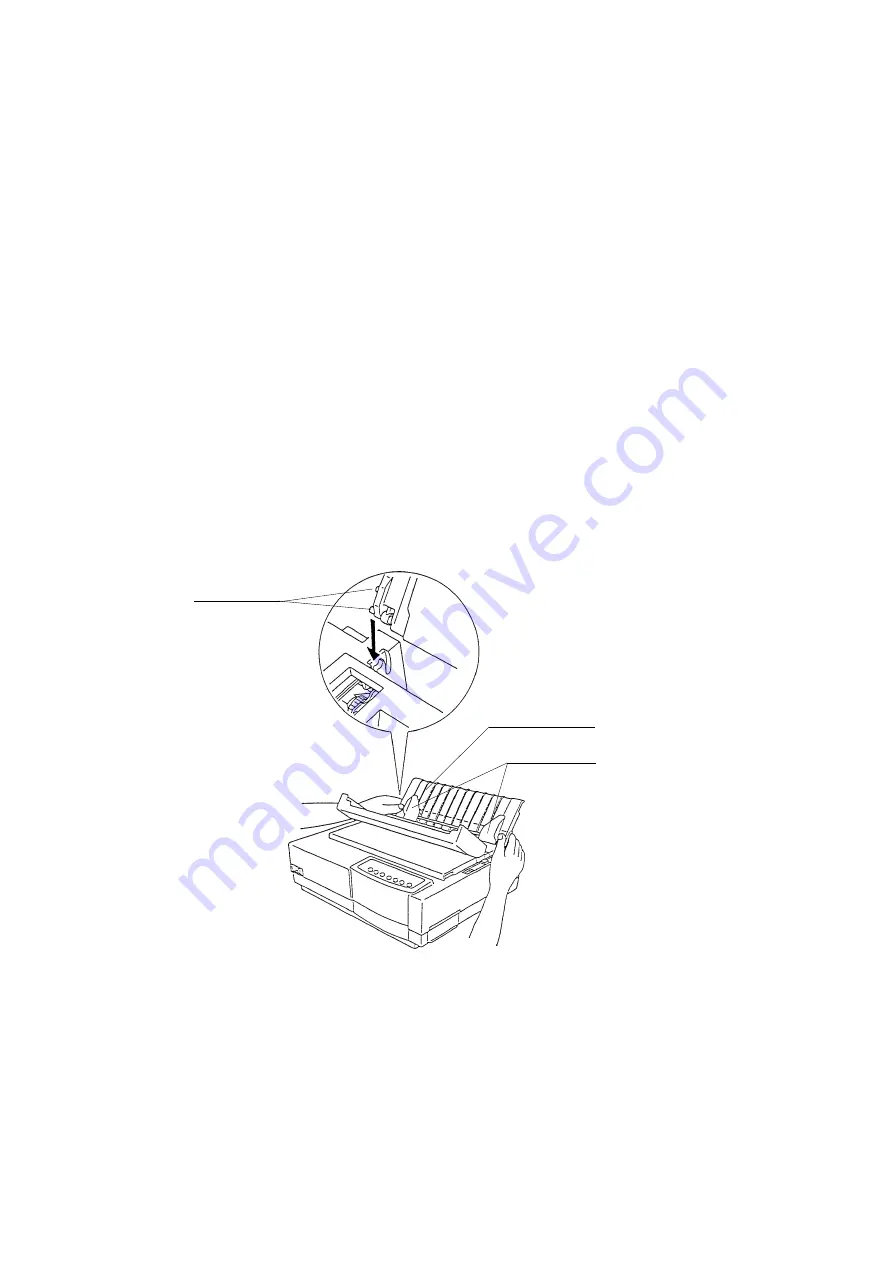
Install the cut-sheet stand (Figure 2.4).  The cut-sheet stand enables smooth feeding of not only cut sheets

but continuous forms, and its paper guides position cut sheets for printing.

3.

Install the platen knob.

4.

Install the ribbon cartridge.  See the User Guide for details.

5.

Check the rated voltage for the printer and AC power outlet, then connect the AC power cord between the

printer and AC power outlet.

6.

Close the front cover.

7.

Turn on the power switch.

8.

Load a cut sheet or continuous forms as explained in the User Guide.

Check printing performance and quality using self-test printing, detailed in Section 4.10.1 “Self-test print-

ing”.

Figure 2.4  Installing the cut-sheet stand

Mounting pins

Cut-sheet stand

Paper guides

Содержание LA30 N

Страница 1: ...Order Number ER LA30N SV 003 Service Manual TM LA30N LA30W Companion Printer...

Страница 2: ......

Страница 3: ...LA30N LA30W Companion Printer Service Manual Digital Equipment Corporation Maynard Massachusetts...

Страница 4: ...roduced in any form without permission Specification No ER LA30N SV Edition 001 002 003 Date published January 1996 July 1996 June 1997 Page P 4 17 19 20 and 27 and P 6 2 Revised contents First issue...

Страница 5: ......

Страница 6: ...LA30N LA30W Companion Printer The topics covered are Chapter 1 Printer specifications performance and configuration Chapter 2 Unpacking performance check and connection Chapter 3 Troubleshooting Chapt...

Страница 7: ...es on Installation 2 1 2 3 Unpacking 2 2 2 4 Inspection after Unpacking 2 4 CHAPTER 3 TROUBLESHOOTING 3 1 3 1 All Indicators Don t Light 3 4 3 2 No Print Head Movement 3 6 3 3 Incorrect Printing due t...

Страница 8: ...acement 4 24 13 Carriage unit replacement 4 25 14 Print head and ribbon feed assembly replacement 4 27 15 Gear assembly replacement 4 28 16 Paper feeder assembly replacement 4 29 17 Card guide replace...

Страница 9: ...n feed 5 4 5 2 4 Paper feed 5 5 1 Continuous forms feeding 5 6 2 Cut sheet feeding 5 8 3 Paper selection 5 9 4 Autoloading 5 10 5 Paper end detection 5 11 5 2 5 Print head gap control paper thickness...

Страница 10: ...Long mode detection 5 37 5 3 9 Control panel control 5 39 5 3 10 Power supply 5 40 1 Surge current prevention 5 40 2 Rectifying and smoothing 5 40 3 Main voltage regulation switching 5 42 4 Protectio...

Страница 11: ...ure 5 5 Paper feed path 5 5 Figure 5 6 Continuous form feeding push feed tractor 5 6 Figure 5 7 Continuous form feeding pull feed tractor 5 7 Figure 5 8 Cut sheet feeding 5 8 Figure 5 9 Paper selectio...

Страница 12: ...5 31 Figure 5 31 Print timing 5 32 Figure 5 32 Phase switching and paper feed direction 5 33 Figure 5 33 Paper feed speed 5 34 Figure 5 34 1 2 phase excitation of paper feed 5 34 Figure 5 35 Phase sw...

Страница 13: ...off 3 15 Table 4 1 Maintenance tools 4 2 Table 4 2 Parts not to be disassembled 4 4 Table 4 3 Cleaning 4 5 Table 4 4 Power on initiated maintenance 4 52 Table 5 1 Memory address map 5 24 Table 5 2 Vol...

Страница 14: ...down Order Number ER LA30N IP 002 LA30N LA30W Companion Printer User Guide Order Number EK LA30E UG 001 The former contains information on location and order number of all parts needed for printer mai...

Страница 15: ...The model configuration varies with the combination of the three options as follows The monochrome model prints in color when the optional color kit is installed Each model has three emulations Digit...

Страница 16: ...color kit option Timing belt Carrier cable assy Relay cable assy SP motor assy space motor assy Stay shaft assy Copy control lever linked to paper thickness lever Sensors Sensor T assy for cut sheet...

Страница 17: ...that it does not obstruct the paper feed path b Front cover The front cover is opened when the ribbon cartridge is installed c Top cover The separator directs the printed paper to the cut sheet stand...

Страница 18: ...one direction regardless of carriage movement The color kit consisting of a color selection shift motor and four color ribbon is installed on the cartridge One of the two sensors detects left right to...

Страница 19: ...mware including resident emulation programs This board has drivers and receivers for other components Sensor receivers convert signals from sensors Drivers supply power to motors print head wires and...

Страница 20: ...t printing Installation requires mini mum time and expense 2 2 Notes on Installation For best results note the following points when installing the printer Place the printer on a level vibration free...

Страница 21: ...serial interface cable and ribbon cartridge 2 Lift out the printer together with its packing cushions not shown in the figure Remove cushions and place the printer carefully on a level vibration free...

Страница 22: ...Cardboard Front cover Figure 2 2 Removing the print head shipping restraint cardboard 5 At the back of the printer remove the two tractor unit securing adhesive tapes A For LA30N printers remove also...

Страница 23: ...4 Install the ribbon cartridge See the User Guide for details 5 Check the rated voltage for the printer and AC power outlet then connect the AC power cord between the printer and AC power outlet 6 Clo...

Страница 24: ...s 3 1 to 3 5 are troubleshooting diagrams The flowcharts show how to determine what is wrong with the printer and what to do to correct the problem Section 3 6 explains error displays on the control p...

Страница 25: ...sm The carriage includes ribbon feed and other sensors The printing mechanism has two motors for driving the carriage and feeding forms b Printer control board The printer control board consists of a...

Страница 26: ...rinter Its specifications depend on the input AC voltage f Color kit user option The color ribbon shift motor installed on the print head cartridge enables printing in seven colors if supported by sof...

Страница 27: ...en insert the power plug into the receptacle The control panel is defective Yes Is the power plug disconnected from the receptacle No Turn off the power switch and then remove the AC fuse Is the fuse...

Страница 28: ...nter Is it correct Are all connectors to the printer control board connected Is DC output voltage of the power supply board correct Defective PC board Defective printer control board Defective control...

Страница 29: ...erface cable Yes Yes No Yes No Connect connectors No Fault indicator light but the print head does not move Does the buzzer sound continuously Are all connectors to the printer control board connected...

Страница 30: ...rinter and press the FF Load button Is the Fault indicator off Does the sensor shield lever move up and down Are the paper end sensor block dusty with paper particles See page 3 5 DC voltage check Pus...

Страница 31: ...data length Use the correct data format No Yes No Yes No Centronics Yes No Yes No Yes No Yes Yes No No printing online Is the interface cable connected Is the interface cable OK Is the RS 423 interfa...

Страница 32: ...cted This may be caused when the interface type specified is the Centronics parallel but the RS 423 serial interface is mistakenly selected internally Printing is not done in specified columns This ma...

Страница 33: ...ibbon feed mechanism Make sure the ribbon cartridge engages the ribbon feed shaft gear Defective ribbon cartridge See page 3 12 See page 3 13 No No Yes Yes No No No Yes No Yes No Yes Yes Yes Printing...

Страница 34: ...ve printer control board Check the host computer Yes Yes No Yes No No No No Yes Yes Yes Yes No No Continued from the previous page Are several character dots missing Is self test printing normal See S...

Страница 35: ...ing abnormal Is the ribbon cartridge installed correctly Is the paper thickness lever set correctly Is the color kit installed correctly See Section 5 2 6 Replace the color kit Dot missing Replace the...

Страница 36: ...ty Load forms correctly Connect the cable correctly Defective printer control board Defective paper feed motor Defective paper end sensor Press the FF Load button Yes No Yes No Yes No No Yes Are forms...

Страница 37: ...Forms are fed but there is still a problem Are unspecified or abnormal forms used Are forms positioned correctly Is something blocking the feed path Defective printer control board Defective paper fe...

Страница 38: ...Display This printer indicates errors on the panel using a combination of the Fault indicator and the buzzer Possible error combinations are described below Table 3 1 Errors indicated by the Fault in...

Страница 39: ...3 16...

Страница 40: ...echanism as the bail roller unit Bail rollers of LA30W are built in the top cover Other components are the same The printer has useful maintenance functions that can be initiated by the control panel...

Страница 41: ...ntenance level 2 2 2 2 2 2 2 2 2 1 1 A magnetized driver is convenient 2 For removing the RS 423 board and the card guide sensor cable holder 3 For fitting the E ring Tweezers are convenient but stand...

Страница 42: ...and their location Figure 4 1 Basic components Carriage Front stay Stay shaft Tractor not visible Platen roll Print head Paper select lever Paper feed motor Space motor Timing belt Printer control bo...

Страница 43: ...screws not to be loosened or removed Table 4 2 Parts not to be disassembled No 1 2 3 4 Components Frame L R Main stay and Front stay SP motor Print head Remarks Screws for holding frame L and R to mai...

Страница 44: ...y shaft and front stay rack rail Procedure Remove paper particles and dirt Remove pieces of paper and dirt from the ribbon Clean with a soft cloth moistened not soaked in alcohol Wipe away ink ribbon...

Страница 45: ...eep assembly areas clean Turn off power to equipment and unplug it before disassembly or assembly Follow procedures carefully Do not disassemble parts that are not to be disassembled Store disassemble...

Страница 46: ...on both side of the acoustic cover into the hook of the top cover After that close the acoustic cover 1 Acoustic cover replacement Removal Raise the acoustic cover vertically the flat surface of the...

Страница 47: ...l up both ends of the tractor unit to detach the catches of the tractor unit from the support studs Then pull the tractor unit Installation Place the catches of the tractor unit onto the support studs...

Страница 48: ...4 9 b Pull tractor Removal Hold both sides of the tractor unit and lift and release it from the support studs...

Страница 49: ...atches of the tractor unit on the support studs near the platen shaft push the tractor unit toward the front of the printer and snap down the tractor unit into place so that the catches click on the r...

Страница 50: ...l 1 Remove the acoustic cover Section 4 9 1 1 2 Remove the tractor unit Section 4 9 1 2 3 Pull off the platen knob 4 Open the front cover and the top cover nearly vertically A then lift and remove the...

Страница 51: ...4 12 5 Raise the cut sheet stand and the back cover together then remove them in the direction of the arrow A...

Страница 52: ...two for LA30N three for LA30W 8 Lift the back part of the upper cover 9 Disconnect the control panel cable from the printer control board and remove the control panel cable from the cable holder 10 R...

Страница 53: ...ind the cable holder Check that the paper thickness lever fits into the copy control lever Check that the side cover is in place Make sure that the box tab on the upper cover fits the hook of the bott...

Страница 54: ...the remove the two screws 3 Remove the control panel Control panel Leaf spring Upper cover Installation Install the control panel in reverse order of removal Notes When replacing the control panel be...

Страница 55: ...sm Installation Install the printing mechanism in reverse order of removal Notes Be sure to connect all connectors to the control board Use cable clamps for the line feed motor space motor and sensor...

Страница 56: ...ies are compatible with each other but their fuses are not compatible For LA30N only before connecting the CNPW connector to the corresponding connector on the control board ROM board be sure to wind...

Страница 57: ...oard replacement Removal 1 Remove the two screws using the screwdriver M2 M2 5 for Phillips screws 2 Unplug the CNRS connector from the control board then remove the RS 423 board RS 423 board Connecto...

Страница 58: ...types of control boards and ROMs respectively control board old and new design boards ROM EPROM and mask ROM Any combinations of a board and ROM s are available Removal 1 Remove the printing mechanis...

Страница 59: ...ns available When replacing the ROM s use either socket IC1 for an EPROM program and socket IC3 for a mask ROM CG or socket IC1 for a mask ROM program and CG The ROM s orientation mark cut must face t...

Страница 60: ...l the right platen bearing off the shaft 5 Move the carriage unit all the way to the right 6 Move the platen roll all the way to the left B and remove the left platen bearing 7 To remove the platen ro...

Страница 61: ...emove the two screws to remove the paper feed motor Installation Install the paper feed motor in reverse order of removal Note Check that paper feed motor gears are engaged Put the motor cable along t...

Страница 62: ...e motor drive pulley then remove the space motor 4 Remove the motor cable from the cable clamp 5 Disconnect the cable connector from the space motor Motor drive pulley Space motor Cable connector Inst...

Страница 63: ...d on the cut sheet stand Removal 1 Remove the tractor unit Section 4 9 1 2 and covers Section 4 9 1 3 2 Remove the two screws to remove the sensor T assembly while disconnecting the sensor wire cable...

Страница 64: ...head Section 4 9 1 14 2 Mark the setting positions of the adjustment levers R and L at both sides of the mechanism For adjustment lever R see the figure on the next page 3 Loosen the screw to remove t...

Страница 65: ...he bracket 10 Remove the tension pulley bracket from the frame by sliding and lifting it in the directions of the arrow 11 Detach the belt from both pulleys Pulley Frame Belt Tension pulley bracket 5...

Страница 66: ...ok Hook Ribbon feed assembly Hook Hook Hook Hook Flexible cable for color unit View A Installation Install the print head and the ribbon feed assembly in reverse order of removal Note Carefully fit pr...

Страница 67: ...mbly includes the LF motor Removal 1 Remove the printing mechanism Section 4 9 1 5 2 Remove the platen assembly Section 4 9 1 9 3 Set the paper select lever toward the back of the printer 4 Loosen the...

Страница 68: ...ove the paper feeder assembly Sensor assemblies Installation Install the Paper feeder assembly in reverse order of removal Notes The paper feeder assembly contains two paper sensor assemblies Make sur...

Страница 69: ...assembly Section 4 9 1 16 2 Remove the small screw which retains the sensor cable on the card guide 3 Push the two hooks outwards to remove the card guide from the carriage unit Card guide Installati...

Страница 70: ...of the ribbon shift unit to raise the top of the unit Hook hidden Installation Install the ribbon shift unit in reverse order of removal Snap down the unit into place Hook hidden 3 Release the other...

Страница 71: ...he left and right To adjust the gap turn the two levers at the ends of the stay shaft Procedure 1 Turn off the printer power switch 2 Remove the covers Section 4 9 1 3 3 Set the paper thickness lever...

Страница 72: ...e frame 11 Move the carriage unit to the center and check the gap If the gap does not satisfy the value return to step 8 12 Move the carriage unit again to the left center and right to confirm the gap...

Страница 73: ...te directions in bidirectional printing Adjust for the three print qualities letter correspondence and draft Procedure 1 Load continuous forms at least 203 mm 8 inches wide onto the printer to avoid p...

Страница 74: ...he right of reverse printing bars press the button to make the vertical line straight 5 Check alignment again If alignment is not still correct repeat step 4 If correct press the button to change to t...

Страница 75: ...ue of TOF currently stored and H s will be printed by a line Pressing the Top button in this condition returns the paper to the park position then reload the paper and overprints H s Use this button t...

Страница 76: ...nts are replaced Lubrication codes are as follows 2 GD D O Cycle Amount 1 drop Type Mobil oil No 1 No Sequential number for the location to be lubricated 2 Type FL Floil SG Silicone grease 3 Amount D...

Страница 77: ...mbly No 1 2 3 Location Gear teeth 4 places Gear bearing 4 places Inside the drum Remarks Amount C C C Oil SG SG SG 1 SG C 0 3 SG C 0 2 SG C 0 Arm Y365 Gear C X330 Idle gear Y363 RF shaft Y364 RF gear...

Страница 78: ...r ribbon shift motor Option No 1 2 3 Location Cam center Gear teeth Cam Remarks Amount C C C Oil SG SG SG 1 SG C 0 2 SG C 0 3 SG C 0 RS motor Asy Shift lever Y393 Color frame R Y391 Eccentric cam Y392...

Страница 79: ...Gear teeth 4 places Gear A B C D Gear bearing 4 places Gear A B C D Gear surface Gear holder boss Remarks Shaded portion Amount C C C C Oil SG SG SG SG 4 SG C 0 2 SG C 0 Motor bracket Y401 Gear A Y421...

Страница 80: ...1 2 Location Sliding section between carriage unit and stay shaft Sliding section between carriage unit and front stay Remarks Oil felt Shaded portion Amount F C Oil FL SG Carriage unit Front stay 2 S...

Страница 81: ...4 42 5 Paper feed roller shaft No 1 Location Feed roller shaft Remarks Amount C Oil SG 1 SG C 0 Holder T Y517 Rear stay T Paper cradle Feed roller R Asy...

Страница 82: ...4 43 6 Shaft No 1 Location lubricated Stay shaft Remarks Amount C Oil FL FG shaft spring Y304 Adjustment lever L Y307 Stay shaft Asy 1 FL C 0...

Страница 83: ...4 44 7 Stay shaft No 1 2 Location Gear holder boss Change lever boss Remarks Amount C C Oil SG SG Change lever Y42003 1 SG C 0 PS Spring Y427 2 SG C 0...

Страница 84: ...4 45 8 Front and top covers LA30N No 1 2 Location Hinge two places Hinge two places Remarks Both sides Both sides Amount C C Oil SG SG 1 SG C O 2 SG C O...

Страница 85: ...4 46 9 Front and top covers LA30W No 1 2 Location Hinge two places Hinge two places Remarks Both sides Both sides Amount C C Oil SG SG 1 SG C O 2 SG C O 2 SG C O 1 to 3 mm...

Страница 86: ...s four places Remarks Wipe off excess oil after applying Wipe off excess oil after applying Wipe off excess oil after applying Amount C C C Oil SG SG SG 2 SG C O Sheet guide 1 SG C O 40 mm 4 mm 6 mm S...

Страница 87: ...ting on the platen 2 Start self test printing one of the following two ways Power on initiated self test Turn on the power switch while holding down the FF Load button Self test in Set Up mode a Turn...

Страница 88: ...r line are printed repeatedly using seven colors black magenta cyan violet yellow orange and green The printed font is determined by a FONT option setting in the current active macro Macro 1 or 2 3 St...

Страница 89: ...ten 2 Set the printer in Hex Dump mode one of the following two ways Power on initiated self test Turn on the power switch while holding down the Protocol and Park buttons Self test in Set Up mode a T...

Страница 90: ...ntil the printer beeps Table 4 4 Power on initiated maintenance Font Pause Macro Protocol Park LF FF Load Level of test User User User User Field Field Field Field Field Field Field User User Field Fi...

Страница 91: ......

Страница 92: ...LA30N and LA30W operation A microprocessor controls the following basic functions Interface Carriage drive Print head drive Paper feed drive Ribbon shift drive color option Figure 5 1 gives the funct...

Страница 93: ...e is drawn in the direction indicated by the arrow and the armature pushes the wire in the same direction The wire is guided to the top of the print head through four wire guides When the armature is...

Страница 94: ...ht corner of the frame through the timing belt The print head carriage is on the stay shaft parallel to the platen and the front stay rack rail fixed on the front of the frame so that it moves in para...

Страница 95: ...Power is transmitted to gear C a planet gear Gear C engages one of two gears depending on carriage movement When the carriage moves from right to left gear C directly engages the ribbon drive shaft g...

Страница 96: ...gear B and the tractor gear When the tractor unit is installed on the top of the platen for use as a pull tractor the platen gear transmits power to the tractor gear through idle gear D This power tra...

Страница 97: ...us forms fed by pin belt tractors advance along the card guide on the carriage then move up over the platen After passing the card guide forms are pinched by the platen and bail rollers to remove slac...

Страница 98: ...ontinuous forms fed from the bottom slot advance along the card guide on the carriage then move up over the platen Figure 5 7 Continuous form feeding pull feed tractor Card guide Card guide Platen Con...

Страница 99: ...ward To pass the printing section the sheet is guided by the card guide and fed further between the bail roller and the platen Cut sheet Figure 5 8 Cut sheet feeding Feed roller For the bail roller it...

Страница 100: ...transmitting rotation to the continuous forms feed tractor At the same time the paper select lever operates the link mechanism then activates the microswitch to indicate the cut sheet select status Th...

Страница 101: ...specified position which is set separately for cut sheets and continuous forms The paper is loaded until it is detected by the reflection photosensor on the card guide Platen Bail roller Reflection p...

Страница 102: ...e paper shields the sensor light path The top edge of paper is detected by sensor B a reflection photosensor on the card guide When paper is not loaded the light emitted from the photosensor is not re...

Страница 103: ...1 s movement is transmitted to the sensor shield lever When there is paper the paper pushes down feeler 1 and the shield lever opens the sensor light path Paper end is detected by feeler 2 on the tra...

Страница 104: ...ensor C detailed in Figure 5 12 It is approximate 35 mm from the print position d Continuous forms fed via pull tractor from the rear side Paper end is detected by feeler 3 linked to sensor C Continuo...

Страница 105: ...nt head gap equal between right end and left end The eccentric stay shaft is also rotated by the copy control lever which is linked to the paper thickness lever The paper thickness lever is set toward...

Страница 106: ...ift lever which lifts the color ribbon cartridge to the location of a selected color one of the four colors If a monochrome ribbon cartridge is loaded the color printer works as a monochrome printer C...

Страница 107: ...a pull tractor Installing the tractor unit at the rear of the printer pushes down the feeler and raises shield plate A as shown below The photosensor on the bottom of the carriage detects this condit...

Страница 108: ...MPU receives data and commands from the host computer and controls the printing mechanism Figures 5 17 and 5 18 Figure 5 17 System configuration Host computer Control panel Interface controller RS 42...

Страница 109: ...d motor Control board main board RC95AA AC input 100 200 VAC or 220 240 VAC CNLF Print head Carriage motor CNSP CNOP RO93BF Control panel CN423 INFCEN Centronics RS 423 RS95AA RS423 CNPW CNHD1 CNHD2 C...

Страница 110: ...and print head pin magnet drivers Figures 5 20 and 5 21 Memory Memory consists of program ROM character generator CG ROM RAM and EEPROM Drivers Drivers include print head and motor drivers and an ala...

Страница 111: ...hermal 34V check 34V check 5V 34V OPLSI LSI1 D RAM Data etc ROM CG ROM Programs Address Data Alarm detector Driver Driver Driver Ribbon shift motor option Carriage motor Paper feed motor Sensors and s...

Страница 112: ...bon shift motor control circuit CS00X 04X IOSX OASX Chip select decoder 8 8 data converter MA00 01 Quasi SRAM and DRAM controller Control panel control citcuit OPDOT SHIFT LOAD RAS CAS CASH LOAD HDTIN...

Страница 113: ...ut port EXIOCS IOWRL IOWRH IORD Address decoder TIMER1 A01 A05 CLK Division circuit D00 D15 IN00 IN04 HDALM00 06 SPALMS SPALML LFALMS LFALML Alarm detection circuit POWST DVALM I O port OUT00 07 FLYBK...

Страница 114: ...LSI Firmware functions are built into the 4M bit ROM and one of the two 16M bit ROMs is reserved for optional CG data 000000 5FFFFF 600000 A00000 C00000 E00000 FFFFFF ROM ROM ROM RAM I O and work RAM...

Страница 115: ...ng Work RAM extended addressing Program access Program access extended RAM extended Program access RAM receive download buffer Size bytes 192 64 640 5 9M 8M 1M 1M Read Write Read Write Read Read Write...

Страница 116: ...dge of the Strobe signal DSTB The BUSY signal goes high The MPU recognizes that data has been received and stores the information in the receive buffer or processes it immediately After the operation...

Страница 117: ...d and stores the information in the receive buffer or processes it immediately The MPU may send out buffer status information such as DC1 DC3 buffer near empty or buffer full from the serial interface...

Страница 118: ...or SPM2 This signal drives phase C of the carriage motor SPM3 This signal drives phase D of the carriage motor SPI1 2 These signals switch the carriage motor phase current Four current levels can be s...

Страница 119: ...al acceleration The excitation period gradually is made shorter Stop Gradual deceleration The excitation period gradually is made longer The motor drive HIC outputs constant current power based on the...

Страница 120: ...phase excitation based on speed Figure 5 27 Speed 10 cpi 2 phase excitation 1 2 phase excitation Time High speed draft Draft NLQ 2 Letter quality cps 330 300 200 100 1 Slewing 2 Near letter quality a...

Страница 121: ...se A A B B C C D D A A B B C C D D A A B C D A B C D A B Figure 5 28 Carriage drive 1 2 phase excitation at low speed SPI1 2 SPM1 A SPM2 B SPM3 C SPM4 D Drive phase D A A B C D A B C D A B C D A B C D...

Страница 122: ...rol LSI being set to high for dots to be printed 3 Excitation and flyback absorption timers are in the HDLSI MBCU20050 4 Print data and excitation time are ANDed and the result is output by the HDLSI...

Страница 123: ...oltage continues even in three pass printing an alarm is generated Figure 5 31 shows the print timing and waveforms of the head pin magnet drive current Toffset HDTIM PD01 PD24 Main excitation FLYBK01...

Страница 124: ...feed motor LFM3 This signal drives phase D of the paper feed motor LFI1 2 These signal switch the paper feed motor phase current Four current levels can be selected for high speed and stop Phase swit...

Страница 125: ...nly one speed Figure 5 33 and driving is always done using 2 phase excitation Figure 5 34 Paper feed speed 5 6 ips Time Figure 5 33 Paper feed speed Figure 5 34 1 2 phase excitation of paper feed Idle...

Страница 126: ...CLM1 This signal drives phase B of the ribbon shift motor CLM2 This signal drives phase C of the ribbon shift motor CLM3 This signal drives phase D of the ribbon shift motor Phase switching is control...

Страница 127: ...ure 5 36 and driving is always done using 1 2 phase excitation Figure 5 37 Ribbon shift speed Time Figure 5 36 Ribbon shift speed Ribbon shift stop Ribbon shift in progress Ribbon shift stop CLM00 0A...

Страница 128: ...ued from the compare circuit to HDLSI MBCU20050 d HDLSI HDLSI outputs the PWSTOP signal to the power supply after recognizing that the alarm signal is received When the PWSTOP signal is output the pow...

Страница 129: ...5 V circuits is turned off to keep the SP and LF motors from burning out Short mode detection 34V 34V 34V SG2 Long mode detection SG2 SG1 SG1 Time constant circuit SG1 5V 5V SG1 SG1 SG1 Time constant...

Страница 130: ...om the main board to the LSI as serial data which the LSI converts into parallel data The switch contact signals are input to the LSI as parallel data which the LSI con verts into serial data and issu...

Страница 131: ...external signal PWSTOP is received from the control board 1 Surge current prevention Figure 5 41 A When power is turned on the charge current flowing into capacitor C3 is limited by the negative temp...

Страница 132: ...fier circuit Surge current preven tion circuit Smooth ing circuit Main switch ing circuit Rectifier circuit Smooth ing circuit Rectifier circuit Smooth ing circuit 3 terminal regulator 5 V 34 V PWSTOP...

Страница 133: ...ing control Self activated flyback converter Voltage 5 V 34 V 4 Protection a Primary circuit protection A fuse is equipped between the power inlet and the power switch The fuse holder is near the powe...

Страница 134: ...5 V 34 V Overvoltage protection OVP If a malfunction occurs in the power control system the following protection starts to prevent overvoltage at the output Table 5 4 Table 5 4 Overvoltage protection...

Страница 135: ...V and 34 V outputs even if problem that can result in power failure occurs outside the power supply When power is turned on the PWSTOP signal is kept low and 5 V and 34 V output go to the prescribed v...

Страница 136: ...ll emulations in CG control bit map scalable image control and bar code pattern generation such as picture drawing The base control group executes BIOS control for the host interface mechanism section...

Страница 137: ......

Страница 138: ...nism LA30N 29 33214 01 LA30W 11 Platen roll assy 29 33036 01 4 9 1 9 Platen LA30N 29 33216 01 LA30W 12 Platen knob 29 33037 01 4 9 1 3 Common 13 Change lever 29 33038 01 4 9 1 15 Paper select lever Co...

Страница 139: ...stand LA30N 29 33222 01 LA30W 26 Timing belt 29 33073 01 4 9 1 13 LA30N 29 33223 01 LA30W 27 Feed roller assy 29 33074 01 4 9 1 16 In paper feeder assy LA30N 29 33224 01 LA30W 28 Relay cable assy 29 3...

Страница 140: ......

Страница 141: ...TM Printed in Ireland...

Отзывы: