background image

12

Setting Up The Expansion Bay

Adding A Hard Drive To Bay #2 & 3

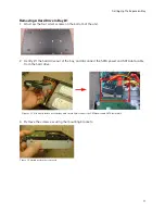
1. Plug in the SATA power connector and SATA data 

connector into the hard drive (Figure 3.5).


Do not force in the connectors. The connectors are 
designed to go in one way only.

2. Lower the hard drive into the bay.
3. Clasp your hand on the hard drive and the casing 

(Figure 3.6).

4. Flip the unit upside down while clasping the hard 

drive with your hands (Figure 3.7).

5. Screw in the four corresponding hard drive screws 

underneath the unit to secure.

Removing A Hard Drive from Bay #2 & 3

1. Flip the unit upside down with the silver screws 

facing up.

2. Clasp your hand on the hard drive and the casing. 

This prevents the hard drive from falling when you 
unscrew it from the case.

3. Remove the four corresponding silver screws.
4. With your hands still clasping the hard drive, flip the 

unit upright.

5. Unplug the SATA power cord and SATA data cord.

SATA Connectors

Sata connectors are designed to connect one way only. 
The connector with the flat, red cable is the data 
connector. The wider connector with the red and black 
wires is the power connector.

Hard Drive Rotation Speeds

If you are setting up the expansion bay in Mirror mode, 
the hard drives must be at least 7200 RPM. Hard drives 
slower than 7200 RPM are not recommended.


Setup Tips

• 

Ground yourself

 from static electricity before 

handling the hard drive. Static electricity may damage hard drives and electronic components.

• 

Keep the exhaust vents clear

. The exhaust fans draw hot air out of the casing and cools the 

hard drive.

• 

Add a UPS (Uninterruptible Power Supply) (Optional) 

to ensure that power outtages do not 

shut off your main system. A UPS can reduce or prevent damage to your equipment from 
sudden power surges.

Figure 3.5 Plug in the SATA power and data cables.

Figure 3.6 Clasp your hands on the hard drive and flip 
over.

Figure 3.7 While holding the hard drive, screw in the 
four screws to secure the hard drive in place.

Figure 3.8 SATA connectors. Data connector shown on 
the left; power connector on the right.

Содержание VBAY3HD

Страница 1: ...Copyright 2009 Digimerge Technology Inc www digimerge com Right For Business INSTRUCTION MANUAL English Version 1 0 HARD DRIVE EXPANSION BAY DESIGNED FOR THE DIGIMERGE BLADE VBAY3HD...

Страница 2: ...REFER SERVICING TO QUALIFIED SERVICE PERSONNEL The lightning flash symbol within an equilateral triangle is intended to alert the user to the presence of uninsulated dangerous voltage within the produ...

Страница 3: ...ced by your service technician 7 Power Cord Protection Power supply cords should be routed so that they are not likely to be walked on or pinched by items placed upon or against them paying particular...

Страница 4: ...ent fire electric shock or other hazards 16 Safety Check Upon completion of any service or repairs to this video product ask the service technician to perform safety checks recommended by the manufact...

Страница 5: ...t the user follows the guidelines in this manual to avoid improper usage which may result in damage to the unit electrical shock and fire hazard injury In order to improve the feature functions and qu...

Страница 6: ...pansion capability total of 3 hard drives not included Mirroring capability duplicates data on your Blade providing secure data redundancy Ultra slim stackable design Rugged metal enclosure Dual exhau...

Страница 7: ...n Bay to Record Events 6 Setting Up The Expansion Bay In Mirror Mode 7 How the Mirroring Sequence Works 7 Error Messages 8 Restarting The Expansion Bay 8 Upgrading The Hard Drive 8 Remove The Casing 8...

Страница 8: ...viii...

Страница 9: ...ER ADAPTER INSTRUCTION MANUAL USB CABLE GROUNDING CABLE HDD SCREWS X12 HARD DRIVE SIZE HARD DRIVE CONFIGURATION MAY VARY BY MODEL PLEASE REFER TO YOUR PACKAGE FOR SPECIFIC CONTENT DETAILS CHECK YOUR P...

Страница 10: ...USB cable from the rear panel of the expansion bay to the rear panel USB port on the Blade TIP The bottom USB port on the rear panel of the Blade offers faster transfer rates NOTE It is highly recomme...

Страница 11: ...th longer USB cables 5 Ground Port Grounds the unit from electric shock Always ground the unit to prevent damage 6 DC12V Power Port Port for 12V power supply included STACKING THE EXPANSION BAY The ex...

Страница 12: ...upgrade Once the firmware upgrade is complete the system prompts you with the message PLEASE RECYCLE DVR POWER 6 Turn off the Blade for five seconds then turn it back on The system flashes a blue prom...

Страница 13: ...xample you may want to record a longer duration of video without the need of mirroring the Blade s primary hard drive To set up the expansion bay as a standalone hard drive Configure the expansion har...

Страница 14: ...on the remote 3 Select HDD Press ENTER on the remote 4 Select HDD CONFIGURATION Press ENTER on the remote A window opens with a list of hard drives Figure 2 1 Hard drives labeled FIXED 00 and FIXED 01...

Страница 15: ...in the third hard drive HD3 in illustration copies data from the Blade When the third hard drive HD3 in the expansion bay is full the first hard drive HD1 begins to copy data from the Blade This proce...

Страница 16: ...st restart the Blade in order to detect the expansion bay hard drives To restart the expansion bay unplug the power cord from the rear panel Wait five seconds before powering back on Always set up the...

Страница 17: ...erneath the unit Bay 1 Bay 2 Bay 3 Figure 2 8 Internal layout of expansion bay with three hard drives installed Note that the hard drive in Bay 1 is upside down This is the correct way of installing t...

Страница 18: ...en the four bracket screws to secure mounting bracket in place Figure 3 0 Install the two mounting brackets on the side of the hard drive NOTE The screws that mount the hard drive to the bracket are l...

Страница 19: ...e unit 2 Gently lift the hard drive out of the bay and disconnect the SATA power and SATA data cable from the hard drive 3 Remove the screws securing the mounting brackets Figure 3 3 Lift the hard dri...

Страница 20: ...Sata connectors are designed to connect one way only The connector with the flat red cable is the data connector The wider connector with the red and black wires is the power connector Hard Drive Rot...

Страница 21: ...1 7A peak Read Write 12V 0 8A typical Power Consumption with 2 HDs installed Start 12V 3 0A peak Read Write 12V 1 2A typical Power Consumption with 3 HDs installed Start 12V 4 4A peak Read Write 12V 1...

Страница 22: ...14 Appendix A VBAY3HD Specifications Appendix A cont d Accessories Ground Conductor Grounding Cable AC Adaptor 12 5A with AC Cord Screws 5W 32 32 for HDD Installation USB 2 0 Cable...

Отзывы: