


ZL0067-0B
PAGE 4
©2011 Veris Industries USA 800.354.8556 or +1.503.598.4564 / [email protected]
03112
Alta Labs, Enercept, Enspector, Hawkeye, Trustat, Veris, and the Veris ‘V’ logo are trademarks or registered trademarks of Veris Industries, L.L.C. in the USA and/or other countries.
TM
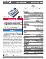
E51
INSTALLATION GUIDE
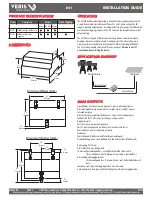
WIRING
To avoid distortion, use parallel wires for control power and voltage inputs.
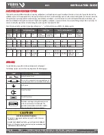
The following symbols are used in the wiring diagrams on the following pages.
Symbol
Description
Voltage Disconnect Switch
Fuse (installer is responsible for ensuring compliance with
local requirements. No fuses are included with the meter.)
Earth ground
X2
X1
Current Transducer
Potential Transformer
Protection containing a voltage disconnect switch
with a fuse or disconnect circuit breaker. The
protection device must be rated for the available
short-circuit current at the connection point.
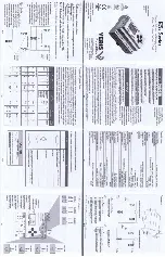
SUPPORTED SYSTEM TYPES
The meter has a number of different possible system wiring configurations (see Wiring Diagrams, page 5). To configure the meter, set the System Type via the User Interface
or Modbus register 130 (if so equipped). The System Type tells the meter which of its current and voltage inputs are valid, which are to be ignored, and if neutral is connected.
Setting the correct System Type prevents unwanted energy accumulation on unused inputs, selects the formula to calculate the Theoretical Maximum System Power, and
determines which phase loss algorithm is to be used. The phase loss algorithm is configured as a percent of the Line-to-Line System Voltage (except when in System Type 10)
and also calculates the expected Line to Neutral voltages for system types that have Neutral (12 & 40).
Values that are not valid in a particular System Type will display as “----” on the User Interface or as QNAN in the Modbus registers.
CTs
Voltage Connections
System Type
Phase Loss Measurements
Wiring
Diagram
Number
of wires
Qty
ID
Qty
ID
Type
Modbus
Register 130
User Interface:
SETUP>S SYS
VLL
VLN
Balance
Diagram
number
Single-Phase Wiring
2
1
A
2
A, N
L-N
10
1L + 1n
AN
1
2
1
A
2
A, B
L-L
11
2L
AB
2
3
2
A, B
3
A, B, N
L-L with N 12
2L + 1n
AB
AN, BN
AN-BN
3
Three-Phase Wiring
3
3
A, B, C 3
A, B, C
Delta
31
3L
AB, BC, CA
AB-BC-CA
4
4
3
A, B, C 4
A, B, C, N Grounded
Wye
40
3L + 1n
AB, BC, CA
AN, BN, CN AN-BN-CN &
AB-BC-CA
5, 6
CAUTION
RISK OF EQUIPMENT DAMAGE
• This product is designed only for use with 1V or 0.33V current
transducers (CTs).
• DO NOT USE CURRENT OUTPUT (e.g. 5A) CTs ON THIS PRODUCT.
• Failure to follow these instructions can result in overheating and
permanent equipment damage.
Содержание ConnectPort X4 IA
Страница 1: ......
Страница 2: ......
Страница 3: ......
Страница 4: ...POWERDASH DAS THREE LINE DIAGRAM ...
Страница 7: ...PVMET 100 2 User s Guide Date 8 10 12 Revision 2 ...
Страница 15: ... 9 ...
Страница 29: ......
Страница 30: ......
Страница 31: ......
Страница 32: ......
Страница 33: ......
Страница 34: ......


