


1
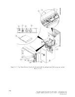
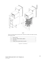
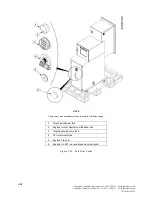
100 to 240 V AC input
2
AC output
3
DC 4 output (18 pin)
4
DC 3 output (14 pin)
5
DC 2 output (16 pin)
6
DC 1 output (15 pin)
7
Hard drive disk (inside of the processor)
8
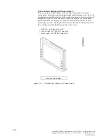
All in one module - consumer display (with touch screen)
9
Hard drive activity LED (red)
10
Processor power LED (green)
11
External DVD/ ROM (optional)
12
Main power (on/off) switch
13
Idle power (on/off) switch
14
Maintenance mode switch
15
Dual USB port 2.0
16
USB port 2.0
17
Rear maintenance display
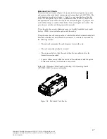
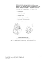
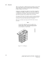
Figure 2-12 Top Chassis Devices Used by the Operator (sheet 2 of 2)
2-15
Copyright ©Diebold, Incorporated (9/2014, 3/2016) - All Rights Reserved
Copyright ©Diebold Nixdorf, Inc. (4/2017, 10/2017) - All Rights Reserved
TP-821765-001D


