


Epsilon-12G2 User Manual Revision A.02
www.diamondsystems.com
Page 10
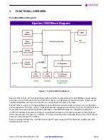
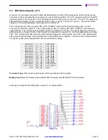
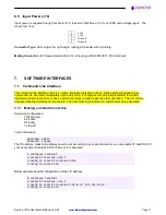
6.4 LED Status Signals (J17)
Connector J17 provides access to the Ethernet LED signals for each of the twelve ports. LEDs may be directly
connected to these signals without requiring any current-limiting resistors. The 3.3V supply required for the LEDs
is also provided by the connector. The control signals pull the LED pin low to turn it on. To use J17 to operate an
LED externally to Epsilon-12G2
, connect the LED’s anode (+) to the 3.3V pin (J17 pin 25). Connect the LED’s
cathode (-) to the corresponding control signal on connector J17.
The on board activity LED is a green LED (LTST-C190GKT) with a typical forward voltage of 2.1V and a
maximum of 2.6V with a 20mA If. The on board speed LED is a Yellow LED (LTST-C190YKT) with the same
characteristics. The control signal is capable of sinking a maximum of 18mA. The series resistor is 330 ohms,
which gives an If of about 3.6mA. When an LED is connected to connector J17, it is in parallel with the on board
LED. If the external LED has about the same forward voltage, the current will be cut in half. If the external LED
has a lower forward voltage, it will dominate the on-board LED and be brighter. Therefore, if the external LED is
not bright enough use an external LED with a lower forward voltage.
Port0_LED1
1
2
Port0_LED2
Port1_LED1
3
4
Port1_LED2
Port2_LED1
5
6
Port2_LED2
Port3_LED1
7
8
Port3_LED2
Port4_LED1
9
10
Port4_LED2
Port5_LED1
11
12
Port5_LED2
Port6_LED1
13
14
Port6_LED2
Port7_LED1
15
16
Port7_LED2
Port8_LED1
17
18
Port8_LED2
Port9_LED1
19
20
Port9_LED2
Port10_LED1
21
22
Port10_LED2
Port11_LED1
23
24
Port11_LED2
+3.3V
25
26
GND
Connector Type:
2mm dual row right-angle, locking pin header with tin plating
Mating Connector:
JST Sales America PUDP-26V-S housing with SPUD-002T-P0.5 terminals
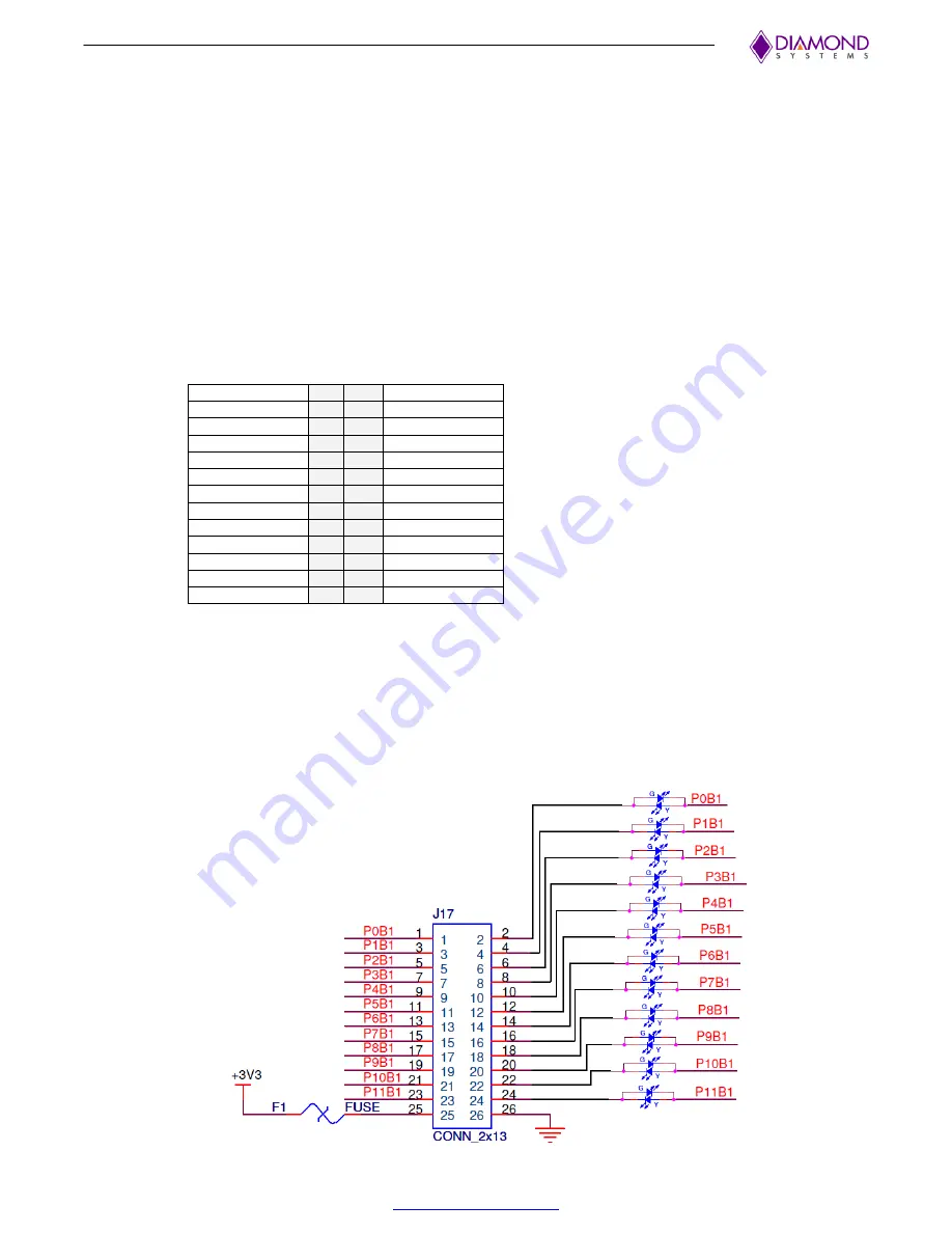
Following is a diagram illustrating how to wire J17 to external LEDs.


