Diamond-MM-48-AT User Manual V1.01
Page 42
16.3 Command Sequences
Diamond Systems provides Universal Driver software to control the counter/timers on
Diamond-MM-48-AT. The information here is intended as a guide for programmers writing
their own code in place of the driver and also to give a better understanding of the
counter/timer operation.
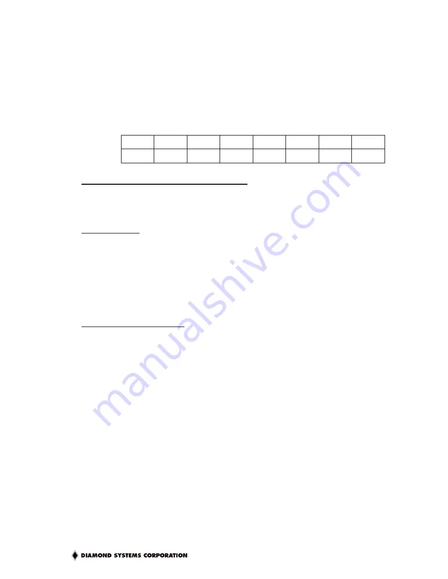
The counter control register is shown below.
Base + 15
Write
Counter/Timer Control Register
Bit
No. 7 6 5 4 3 2 1 0
Name CTRNO
LATCH
GTDIS
GTEN
CTDIS
CTEN
LOAD
CLR
To make a counter run (load and enable a counter)
1. Load the desired initial value into the counter.
2. If you want to use the gate function, enable the gate.
3. Enable the counter.
To read a counter
1. Latch the counter. The counter continues to operate.
2. Read the value from the data registers.
A counter may be enabled or disabled at any time. If disabled, the counter will ignore
incoming clock edges.
The gating may be enabled or disabled at any time. When gating is disabled, the counter will
count all incoming edges. When gating is enabled, if the gate is high the counter will count all
incoming edges, and if the gate is low the counter will ignore incoming clock edges.
Loading and enabling a counter
For counter 0, three bytes are required to load a 24-bit value. For counter 1, two bytes are
needed for a 16-bit value. The value is an unsigned integer.
a. Write the data to the counter:
Break the load value into 3 bytes, low, middle, and high (two bytes for counter 1). Then
write the bytes to the data registers in any sequence.
Counter 0
Counter 1
outp(base+12,low); outp(base+12,low);
outp(base+13,middle); outp(base+13,high);
outp(base+14,high);
b. Load the counter:
Counter 0
Counter 1
outp(base+15,0x02); outp(base+15,0x82);
c. Enable the gate if desired:
Counter 0
Counter 1
outp(base+15,0x10); outp(base+15,0x90);
d. Enable the counter:
Counter 0
Counter 1
outp(base+15,0x04); outp(base+15,0x84);

