Diamond-MM-48-AT User Manual V1.01
Page 37
13. DIGITAL I/O OPERATION
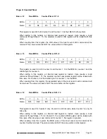
Diamond-MM-48-AT contains a 4-bit digital I/O port with programmable direction and edge
detection capability. The digital I/O lines are located at pins 35 through 38 on the I/O header
J3. They are CMOS / TTL compatible. Each line can drive up to -6mA in a logic high state or
sink up to 8mA in a logic low state. All digital input lines have 10K
Ω
pull-up resistors. The I/O
lines are written and read with 4 bits in the register at Base + 5.
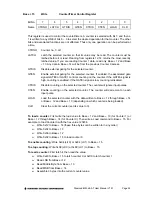
To use the digital I/O lines for simple I/O, set the desired direction using the control register in
Base + 4. Each bit’s direction may be set independently with the control bits DIR3-0 in this
register. On power-up or system reset, all lines are set to input mode.
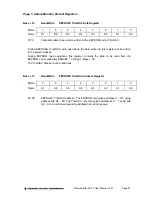
To enable edge detection, set the DINTE bit in Base + 11. When DINTE = 1, any change of
state on any input line will generate an interrupt and set the DINT bit in Base + 11. The
interrupt routine reads the data by reading from Base + 5, and then it clears the interrupt
request by writing a 1 to the CLRD bit in Base + 11. When DINTE = 0, any pending interrupt
request will be cleared, and further changes in state on the input lines will not generate
interrupts.
NOTE:
Diamond-MM-48-AT has 4 distinct interrupt circuits that may request interrupt service
independently of each other. A PC/104 bus interrupt request will occur when any one of the
circuits requests service. As long as any circuit is still requesting service, the interrupt request
will stay active. This means that writing to the CLRD bit may not clear the bus interrupt
request even though it clears the specific digital input interrupt request. The interrupt service
routine is responsible for determining which of the three circuits is requesting service and
handling all of them as needed.

