Diamond-MM-48-AT User Manual V1.01
Page 27
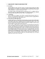
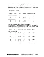
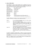
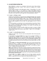
7. ANALOG INPUT RANGES AND RESOLUTION
7.1 Resolution
Diamond-MM-48-AT uses a 16-bit A/D converter. This means that the analog input voltage
can be measured to the precision of a 16-bit binary number. The maximum value of a 16-bit
binary number is 2
16
- 1, or 65535, so the full range of numerical values that you can get from
a Diamond-MM-48-AT analog input channel is 0 - 65535.
The smallest change in input voltage that can be detected is 1/(2
16
), or 1/65536, of the full-
scale input range. This smallest change results in an increase or decrease of 1 in the A/D
code, and so this change is referred to as 1 LSB, or 1 least significant bit.
7.2 Input Ranges
Diamond-MM-48-AT is available in two models. The default model has bipolar inputs of +/-
10V and +/-5V, selectable with jumper block J10. An optional model with a slightly different
component configuration has unipolar inputs of 0-5V.
7.3 Single Ended and Differential Inputs
A single-ended input is a two-wire input (one input signal and ground) that is referenced to
analog ground on the board. This means that the input voltage will be measured with respect
to the board’s analog ground. A differential input is a three-wire input (input +, input -, and
ground), and the board will measure the difference between the voltages of the two inputs.
Diamond-MM-48-AT works only with single-ended inputs.
In some cases, a differential input can be simulated by connecting the high and low input
wires to two adjacent analog input channels, measuring both of them with and A/D scan
operation, and subtracting the low reading from the high reading. This will work only for very
slow changing (or DC) signals with very low noise. The problem with this technique is that the
two signals are sampled at different times, either 5
µ
s or 9.3
µ
s apart depending on the setting
of the SCANINT register bit. This time delay can lead to measurement errors due to the
change in the input signal during the delay. For example, an input signal consisting of a 1KHz
sine wave with 10V amplitude has a maximum slope of 10V x 2 x
π
x 1000Hz = 63,000
V/sec, or 63 mV/
µ
s. This represents a change of 315mV during the 5
µ
s delay between the
sampling of the high input and the low input. For a 16-bit A/D converter on a +/-10V input
range, this is an error of over 1,000 counts.


