


5750-212
Revision A
Page 5
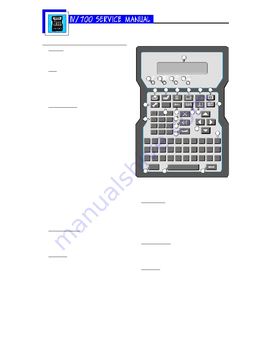
Keypad Assignments
DISPLAY
1 Two-line, twenty character per line, liquid crys-
tal display (LCD).
LEDs
2 Power LED; lit when the printer has power.
3 Photo-eye LED; on while a product passes by.
4 Print LED; lit when the printer is in print mode.
5 Ink out LED; blinks when the ink can is out of
ink.
FUNCTION KEYS
6 PRINT: Starts and stops printing.
7 EDIT: Create, edit or delete a message.
8 PURGE: Purge all ink channels; with ALT (24),
it purges single channels.
9 MESSAGE INDENT: Sets the message indenta-
tion from the leading edge of the product.
10 FONT: Selects the font to print.
11 TIME: Inserts the printed time into a message.
With ALT (24), it inserts a work shift code.
12 SET-UP: For configuration of the system.
13 INFORMATION: Provides status and setting
information.
14 DOT SIZE: Increases or decreases all dot sizes
at once.
15 CHARACTER WIDTH: Changes the width of
printed characters which produces changes in
the length of printed messages.
16 DATE: Inserts the date into a message. With
ALT (24), it inserts an expiration date.
17 ITEM COUNT: Inserts the item count into a
message. With ALT (24), it inserts pallet
counts.
NUMERIC KEYPAD
18 Keys for number entry which will show alter-
nate characters when scrolled with the arrow
keys (22).
EDIT KEYS
19 DELETE: Erases the character under the cur-
sor and does not repeat.
20 BACKSPACE: Deletes the character to the left
of the cursor and will continue to delete when
held down.
21 ENTER: Completes entries and enacts changes.
ARROW KEYS
22 Keys that provide cursor movement and screen scroll-
ing.
ALPHABETIC KEYS
23 Keys for character entry. Each character will show
alternate characters when scrolled with the up and
down arrow keys.
ALTERNATE KEYS
24 ALT: Provides alternate characters and functions when
used in combination with other keys.
25 ENTER: This key duplicates the function of key 21
SPACE BAR
26: Enters spaces in messages; can be scrolled with the
up and down arrows to show alternate characters
Alt
Z
X
C
V
B
N
M
/
(
“
A
S
D
F
G
H
J
K
L
:
W E
R
T
Y
U
I
O
P
Q
.
0
-
1
2
3
4
5
6
7
8
9
i
ABC
ABC
1 2
1 2 3
1
2
3
4
5
6
7
8
9
10
11
17
16
15
14
19
13
21
20
12
18
23
24
26
25
22
Содержание I.V./700
Страница 4: ...5750 212 Revision A Page 4 I V 700 Components...
Страница 26: ...5750 212 Revision A Page 26 Hardware Block Diagram HBD1...
Страница 29: ...5750 212 Revision A Page 29 Parts Drawings General Assembly 30 Controller Assembly 31 Printhead Assembly 32...
Страница 30: ...5750 212 Revision A Page 30 Modular Parts Kits...
Страница 31: ...5750 212 Revision A Page 31 Controller Assembly...
Страница 32: ...5750 212 Revision A Page 32 Printhead Assembly...
Страница 33: ...5750 212 Revision A Page 33 Test Results Declaration of Conformity 34 Inchscape Testing Services 35...
Страница 34: ...5750 212 Revision A Page 34...
Страница 35: ...5750 212 Revision A Page 35...


