Dhollandia DH-L 3300 lbs Скачать руководство пользователя страница 4


DHOLLANDIA 

1


UNDERSTANDING SAFETY AND WARNING SIGNS 


Many safety signs and symbols used in this manual are based on international standards, others refer to specific situations or 
actions. 


Consult appendix 16.1 on page 61 for an overview of signs and symbols used in DHOLLANDIA manuals, and their meaning. Make 
sure you understand these signs and symbols prior to starting the installation. 


Please take special notice of the following signs used in the manual. They indicate the likelihood and severity of a potential injury if 
a person fails to follow the instructions presented on the safety sign. 
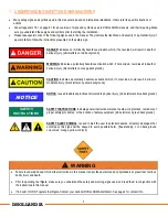


DANGER

: indicates an imminently hazardous situation which, if not avoided, will result in death or 

serious injury. [white letters on red background] 


WARNING

: indicates a potentially hazardous situation which, if not avoided, could result in death or 

serious injury. [black letters on orange background] 


CAUTION

: indicates a potentially hazardous situation which, if not avoided, could result in minor or 

moderate injury. [black letters on yellow background] 


NOTICE

: is used to address practices not related to physical injury. [white letters on blue background] 


SAFETY INSTRUCTIONS

: indicate general instructions relative to safe work practices, reminders of 

proper safety procedures, or the location of safety equipment. [white letters on green background] 


SAFETY ALERT SYMBOL

: is used to alert the user to potential hazards. All safety messages that 

accompany  this  sign  shall  be  obeyed  to  avoid  possible  harm.  [free-standing,  or  on  back-ground 

colours red, orange, yellow or black] 
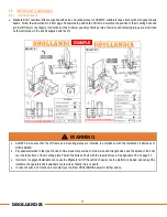


WARNING 


Failure to understand and to follow the instructions in this manual can put the operator and any bystanders at great risk of serious 
bodily injury and death.  


Prior to operating the liftgate, make sure you understand the safety and warning signs used, and read them in conjunction with 
the instructions in this manual.  


If in doubt, DO NOT operate the liftgate. Contact your national DHOLLANDIA distributor. See page 4 for contact info. 
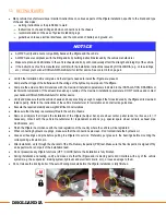
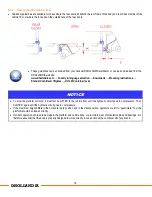


NOTICE 

SAFETY 

INSTRUCTIONS 

Содержание DH-L 3300 lbs

Страница 1: ...LLATION MANUAL Read the manual in its entirety before operating the liftgate Keep this manual in the vehicle cab as reference for the driver and liftgate operator Manufacturer DHOLLANDIA US L L C E ma...

Страница 2: ...f the seal kit 21 7 4 Method with horizontal platform 22 8 MOUNTING OF THE LIFT FRAME 23 8 1 Introduction 23 8 2 Positioning of the lift frame with OAM010 24 8 3 Fixation of the mounting plates OAM010...

Страница 3: ...ERATE sign 60 16 APPENDIX 61 16 1 Meaning of the safety and warning signs 61 16 2 Prescribed torque values for bolts and nuts 63 16 3 Electric and hydraulic requirements 64 16 4 Grease plans 66 16 5 C...

Страница 4: ...a potentially hazardous situation which if not avoided could result in minor or moderate injury black letters on yellow background NOTICE is used to address practices not related to physical injury w...

Страница 5: ...s regarding the installation operation repair and maintenance of DHOLLANDIA liftgates or to obtain replacement copies of manuals or decals DHOLLANDIA US LLC United States West 12968 Santa Ana Avenue F...

Страница 6: ...aims liability for any personal injury death or property damage that results from improper use of the liftgate or negligence to apply the precautions and instructions of the operation manual DHOLLANDI...

Страница 7: ...tact the national DHOLLANDIA distributor for a copy of the latest set of instructions see contact info on page 4 or download the latest edition from the DHOLLANDIA website www dhollandia com Country l...

Страница 8: ...overalls protective gloves adequate ear protection a safety helmet when working under the vehicle chassis NEVER wear loose fitting clothes that may get trapped in the moving parts of the liftgate or...

Страница 9: ...WAYS grind off the galvanization from the areas to weld Most liftgates are equipped with thermoplastic hoses that can be damaged by hot metal chips welding sparks and slag Damage to a hose can lead to...

Страница 10: ...arm length cth Chassis Total Height Actual height from underside of chassis to top of the vehicle floor mfc Mounting height Floor to center of lift arm Mounting height of lift frame under the vehicle...

Страница 11: ...th power pack in premounted position bci Body Cut Inside Width of the mid panel between the lift arms bcw Body Cut Width Width of the cut outs for the lift arms and tilt cylinders blb Body Light Boxes...

Страница 12: ...for further advice Verify and make sure that the vehicle chassis and body are strong enough to support the forces induced by the liftgate at its maximum rated capacity Refer to the instructions of the...

Страница 13: ...N DRAWING sent upon the order confirmation will provide you with the critical installation dimensions that should be observed If no installation drawing is available use the DHOLLANDIA POCKET GUIDE pa...

Страница 14: ...respect the maximum installation parameters vfh mfc mcg Study the image below explaining how mfc and mcg are correctly measured ALWAYS make sure you comply with applicable bumper bar regulations and...

Страница 15: ...rs cross the rear cross member of the vehicle floor this rear cross member must be restricted in height to dimension lft This lft depends on the mounting height mfc and the position of the platform be...

Страница 16: ...15 DHOLLANDIA 6 2 COMMON INSTALLATION DIMENSIONS Listed below are common models offered by DHOLLANDIA US and their associated fitting ranges LMM 33 LMH 33 44...

Страница 17: ...16 DHOLLANDIA LMS 55 66...

Страница 18: ...lift WARNING ALWAYS make sure that the lift frame and mounting plates are installed in accordance with the installation instructions of DHOLLANDIA Pay special attention to the type of bolts minimum qu...

Страница 19: ...dard cantilever liftgates DH LM Container locks NOTICE To stow the platform correctly it must first be LIFTED to the vehicle floor until the hydraulic circuit goes in overpressure Then CLOSED again un...

Страница 20: ...atforms with extended edge options OAP312 OAP313 OAP407 etc require method 3 7 1 METHOD WITH THE FITTING JIGS Measure the outside width across the lift arms This dimension corresponds with the inside...

Страница 21: ...the INSTALLATION DRAWING and in the POCKET GUIDE Next raise the platform and position it onto the supports Slide a spacer D 5mm see above between the platform and the rear frame of the body Adjust an...

Страница 22: ...latform With fitting jig With vertical platform INSTALLATION DRAWING without seal kit INSTALLATION DRAWING with seal kit If an INSTALLATION DRAWING is available the required spacer Q for original DHOL...

Страница 23: ...loor Slide the required spacer between the rear cross member and the platform Secure the platform and prevent it from falling by means of an overhead crane hoists forklift with slings etc Centre the p...

Страница 24: ...haped chassis beams Trailer chassis with I shaped chassis beams Universal mounting plates OAM010 Special execution with option ref OAU009 Mounting plates are not adjustable in longitudinal direction T...

Страница 25: ...2 Dismount the pins for the lift arms from the platform hands Raise the lift arms 3 to the fitting jigs 4 or to the platform hands depending on the chosen installation method Slide the articulation pi...

Страница 26: ...to the vehicle floor In case of bolt on mounting plates fit the mounting plates over the frame by means of the bolts and nuts supplied in the kit bag Do not tighten the bolts and nuts at this stage M...

Страница 27: ...anyhow note that liftgate might be equipped with thermoplastic hoses Observe the important precautions in 4 on page 6 Ensure that the lift frame is correctly centered under the vehicle chassis and bo...

Страница 28: ...27 DHOLLANDIA...

Страница 29: ...nd the spread of the bolts over the full surface of the mounting plate Fasten the bolts and nuts with the required torque see values for shear Maximize the spread of the mounting bolts over the full s...

Страница 30: ...tened in height but with respect for the instructions in this section NOTICE Various vehicles manufacturers offer pre punched chassis and don t allow you to drill additional holes through the chassis...

Страница 31: ...subframe Drill the holes of the drill bit M value of the bolts 1 64 0 5mm Fit the mounting plates bolts and nuts to the vehicle chassis and subframe Fasten all bolts and nuts with the required torque...

Страница 32: ...s overlapping the subframe must be additionally fastened 1 By adding 2 additional bolts per instructions below 2 By welding 2 seams connecting the mounting plates with the subframe per instructions be...

Страница 33: ...le body require adequate anti corrosion protection Make sure you comply with the instructions of the vehicle manufacturer ALWAYS protect and cover thermoplastic hoses with a welding blanket Inspect th...

Страница 34: ...applicable legislation and refusal of the vehicle upon inspection It can put other parties in traffic at great risk and could result in sever injury or death 8 6 2 Towing hitch with OAM010 mounting pl...

Страница 35: ...tion to the type of bolts minimum quantity per side minimum size and strength class and position Fasten the bolts and nuts with the required torque see values for shear If the towing hitch must be rep...

Страница 36: ...a separate kit or if adjustments are required observe the installation instructions sent upon order confirmation or contact your national DHOLLANDIA distributor for a copy of the dedicated mounting i...

Страница 37: ...OR INSTALLATION MAINTENANCE AND REPAIR manual In case of doubt contact the national DHOLLANDIA distributor for further assistance WARNING The platform and the lift frame are very heavy When falling on...

Страница 38: ...an alternative push the piston rod in or pull it out manually as follows 1 Open the safety valves on the lift cylinders manually see below 2 Loosen up the hydraulic couplings of the hoses connected to...

Страница 39: ...le in the tilt cylinders with the hole in the platform hands by means of the electrical controls or manually see procedure above Mount the pins of the tilt cylinders The rollers are mounted and the bo...

Страница 40: ...stops at the rear cross member of the vehicle body Self fabricated end stops bolted welded to the chassis or subframe Self fabricated adjustable end stops mounted to the vehicle chassis or subframe N...

Страница 41: ...thin 2 50 mm from the articulation point of the lift cylinder are not possible a hard stop against the rear cross member of the vehicle floor is required 10 2 PLATFORM STOW POSITION If applicable moun...

Страница 42: ...detach both tilt cylinders from the platform unless it is hung up on a gantry crane with hoists a fork lift with slings etc The stroke of the tilt cylinders 1 is most easily adjusted while they are d...

Страница 43: ...ign the wholes in the adjustable extensions 4 with the holes in the platform hands Mount the pins of the tilt cylinders 1 and the rollers in the same way as originally supplied See also 9 from page 36...

Страница 44: ...or safe operation practices 3 methods are available to mount the stabilizing legs to the lift frame OAH014 01 stabilizing legs are mounted with fixed brackets on the lift frame OAH014 02 stabilizing l...

Страница 45: ...so that you end up with a positive ground clearance d when the stabilizing legs are fully lowered down Follow the bolt instructions below to mount the stabilizing legs to the lift frame Preferably use...

Страница 46: ...switch Dual toggle switch control box to be combined with a cabin switch Optional separate main external control box with main battery disconnect switch Premounted on the lift frame no extra work requ...

Страница 47: ...quired torque Option OAM025 offers a quick fit bracket to mount the control box on the bumper tube 11 2 INSTALLATION OF THE BATTERY CABLE AND GROUND CABLE APPENDIX 16 3 on page 64 provides important i...

Страница 48: ...and the ground cables 2 Make sure this conduit is suitable for automotive purposes and its class is adapted to possible sources of heat nearby In case of doubt contact your national DHOLLANDIA distrib...

Страница 49: ...48 DHOLLANDIA...

Страница 50: ...lectrical cables ALWAYS make sure they make a downward curb as they exit the control box or power pack so that water can drop off in a natural way This is an easy way to prevent water ingress through...

Страница 51: ...LANDIA contact the vehicle importer or DHOLLANDIA for further advice When installing cables make sure these cannot be cut squeezed chafed heated and melted or damaged otherwise by the equipment mounte...

Страница 52: ...51 DHOLLANDIA 11 3 1 Installation of 3 Button Wander Lead OAE002 E0784 M S...

Страница 53: ...52 DHOLLANDIA 11 3 2 Installation of cabin cutoff switch OAE510 15 E0393 S 15...

Страница 54: ...ect the problem prior to continuing Air might be trapped in the hydraulic circuits as long as the liftgate has not been bled Air can cause the platform to make unexpected movements and can put the ins...

Страница 55: ...ls as indicated in the MAINTENANCE AND REPAIR MANUAL Refer to appendix 16 4 from page 66 onwards for relevant grease plan of the liftgate or download any from the website www dhollandia com Country la...

Страница 56: ...e platform closes correctly in stow position Make sure that the platform will be clearly visible in public traffic 1 Apply the RD WH reflective marking tape on both sides of the platform 2 Install the...

Страница 57: ...SERV G 003 of the MAINTENANCE AND REPAIR MANUAL or contact your national DHOLLANDIA distributor for help See contact info on page 4 Apply the safety decals to the liftgate and vehicle body before deli...

Страница 58: ...safety decals to the liftgate and vehicle body in accordance with the instructions below Note the decals marked as EXAMPLE can vary in function of the maximum rated capacity of the liftgate or the ch...

Страница 59: ...58 DHOLLANDIA EF0583 LM EN EF0565 EN EF0620 EN EF0580 EN CAP...

Страница 60: ...59 DHOLLANDIA EF0585 US Serial Number EF0581 EN EF0563 EN EF0616 EF0562 EN...

Страница 61: ...y and that no maintenance or repair is required see 7 6 located in the OPERATION MANUAL If any unsafe condition exists or unusual noises or movements are noticed DO NOT use the liftgate and affix the...

Страница 62: ...rail Protect yourself from falling off the platform or vehicle floor Crushing shearing hazard Keep feet away from moving parts Wear safety gloves Slipping hazard Wear safety toe shoes Tripping hazard...

Страница 63: ...linder SLIDE OUT the platform Unlock Disengage the mechanical locking system SLIDE IN the platform Lock Engage the mechanical locking system Push the stabilizing LEGS DOWN Switch ON the electrical pow...

Страница 64: ...d in conformance with required torque Retighten if required Use a calibrated torque wrench to tighten bolt and nut connections to the prescribed torque value NOTICE WARNING Incorrect too soft or too h...

Страница 65: ...bles Size electric motor Cable section 500 W 16 mm 5 AWG 12V 1200 2000 W 1100 3300 lbs capacity length 33 ft 1100 3300 lbs capacity length 33 60 ft Capacity 3300 lbs Length 60 ft 3 AWG 1 AWG 0 1 0 AWG...

Страница 66: ...the liftgate but often overlooked in troubleshooting Make sure you take these into consideration when executing repairs or maintenance checks DHOLLANDIA mainly uses 3 types of oils in its hydraulic s...

Страница 67: ...H LM 3300 6600 lbs 1500 3000 kg A copy of the grease plans can also be obtained from the national DHOLLANDIA distributor see contact info on page 4 or downloaded from the DHOLLANDIA website www dholla...

Страница 68: ...67 DHOLLANDIA...

Страница 69: ...68 DHOLLANDIA...

Страница 70: ...the back plate of the power pack by means of an Allen key nr 4 Unscrew the bolt and nut completely From the outside unbolt the 2 vertical Allen bolts that hold the 2 main elements of the entry seal t...

Страница 71: ...ber grummets are repositioned correctly after passing the cables A If no main battery disconnect switch connect the battery cable to the incoming terminal of the starter solenoid see B below Connect t...

Страница 72: ...ed in their assigned channel If the nut was dismounted or had become dislocated insert it back into its socket At the inside mount the Allen bolt back in its original position Tighten the bolt firmly...

Страница 73: ...ter to drip off in a natural way Thus you can easily prevent water ingress in the connections of the battery cables NOTICE To ensure the reliability of the lift over many years it is extremely importa...

Страница 74: ...of the main battery disconnect switch Fasten the M8 bolt connection torque 17 7 Ft Lbf 24 N m Slide the heat shrink hose over the connection bolt up to the incoming pole 3 of the main battery disconn...

Страница 75: ...control box to allow water to drip off in a natural way Thus you can easily prevent water ingress in the connections of the battery cables 1 and 5 NOTICE To ensure the reliability of the lift over man...

Страница 76: ...the vehicle body This handgrip will enable the operator to maintain 3 points of contact while travelling on the platform in accordance with the operation manual The handgrip is normally foreseen by t...

Страница 77: ...inside the control box or power pack Replacement copies can be obtained from your national DHOLLANDIA distributor or downloaded from our website If in doubt where to find your national DHOLLANDIA dis...

Страница 78: ...Frequency OK Corrected Main external control box cover installation to vehicle body Condition fastening to the vehicle body undamaged 180 days 3500 cycles Main battery disconnect switch in control box...

Страница 79: ...ections in pump unit electric connection board Condition all connections tight dry and corrosion free 180 days 3500 cycles Limit switches pressure switches tilt sensors optional Condition operation au...

Страница 80: ...ation instructions fastened with required torque 180 days 3500 cycles 9 Platform Frequency OK Corrected Platform construction Condition undamaged no deformation cracks in material or welds no corrosio...

Страница 81: ...m load Lift the platform Check if lift capacity is sufficient Check general operation and stability Check safe working speeds Lift lower max 6 sec Hydraulic open and close max 10 sec Auto tilt at grou...

Страница 82: ...ions Partial works or inspections to follow Maintenance or inspection performed by Service center Name of technician Date of next maintenance inspection Safety first ALWAYS follow the instructions and...

Отзывы: