DFI MDPi Series Скачать руководство пользователя страница 19

19

Chapter  6  

OSD menu operation

User's Manual | MDPi Series

Chapter 6 - OSD menu operation


X

6.1 On-Screen Display

The LCD monitor features an On-Screen Display (OSD) menu with easily identifiable icons 

designed to make adjustment of your monitor display settings a more user-friendly process. 

When highlighted, the icon illustrates the control function and brief instruction to assist the 

user in identifying which control needs adjustment.

The OSD menu is activated by pressing the Control Dial inward and you can select and adjust 

the function of your choice by rotating and clicking the Control Dial. The main menu displays 

a list of sub menu icons and the current video input mode. Rotate the dial to move the high-

lights to the control you would like to adjust, then press the Control Dial inward to select that 

control or to activate that function. Depending on the control you selected, a submenu of the 

control with a status bar will appear. The status bar indicates in which direction, form the fac-

tory preset; your adjustments arebeing made. Rotate the Control Dial to adjust the control.

When you have finished making the adjustments, the setting is saved automatically by ac-

tivating the control function. If you do not touch the Control Dial for 30 seconds, the OSD is 

automatically exited saving your current settings.


X

6.2 Menu Descriptions

The LCD monitor is capable of accepting VGA, DVI(HDMI), Display Port signal inputs and 

therefore has two different sets of OSD control functions. Because the digital signaling al-

ways achieves optimum display quality without mush adjustment, it requires much less OSD 

functions than the analog input mode. The following options are not available in digital input 

mode: Auto Setup, Display, Clock/Phase, denoted by as trick (*) in the following descriptions. If 

switched to digital input model, you will

encounter a “Not Available” message.

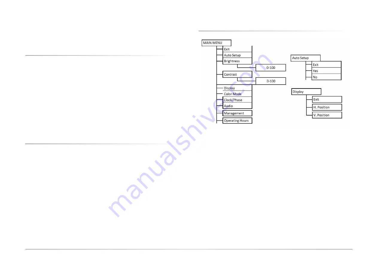
The Charts displays the function tree and brief explanations of the functions. Color, OSD, and 

other adjustments have submenus under each tree.


X

6.3 OSD Structure

Содержание MDPi Series

Страница 1: ...True Flat Healthcare Display with color calibration User s Manual MDPi Series ver A_MP_3 1521_13 13...

Страница 2: ...fication purpose only and are the properties of the respective owners Notice 1 The changes or modifications not expressly approved by the party responsible for compli ance could void the user s author...

Страница 3: ...r 4 Monitor Installation 15 4 1 Cleaning instructions 15 4 2 Stand removal VESA mount installation 16 Chapter 5 Daily operation 18 5 1 Main power switch 18 5 2 Power Status indication 18 Chapter 6 OSD...

Страница 4: ...ortable on a table Intended location Medical environment Intended User Profile Intended User Profile X 1 2 Box of contents 21 5 23 8 27 LCD Touch Screen Monitor AC Power Cord VGA Cable DVI or HDMI Cab...

Страница 5: ...ION Chapter 1 INTRODUCTION Side View The image below shows the control keys located in the right bottom corner of the display 1 Menu Enter key Scrolling key Rear View 1 Rear cover 2 IO cover 3 Monitor...

Страница 6: ...User s Manual MDPi Series 6 Chapter 1 INTRODUCTION Available Connections 1 USB 2 RS232 3 Audio 4 Display Port 5 DVI 6 HDMI RGD model 7 VGA 8 POWER 9 User s Manual MDPi Series...

Страница 7: ...AC Input External power adapter 100 250V External power adapter 100 250V External power adapter 100 250V Power Consumption 40W Max 40W Max 40W Max Mechanical Chassis Material Plastic ABS Plastic ABS P...

Страница 8: ...8 Chapter 1 INTRODUCTION User s Manual MDPi Series X 1 5 Outline Dimension...

Страница 9: ...s and receptacles The power supply cord should be replaced by the designated operator only at all time Use a power cord that matches the voltage of the power outlet which should be approved and in com...

Страница 10: ...indicates that under the European Directive 2012 19 EU governing waste from electrical and electronic equipment this product must not be disposed of with other municipal waste Please dispose of your...

Страница 11: ...determined by turning the device off and on the user is encouraged to try to correct the interference by one or more of the following measures Reorient or relocate the receiving antenna Increase the...

Страница 12: ...WEEE Waste Electrical and Electronic Equipment directive Indicates Direct Current DC Indicates Alternating Current AC Stand by Power ON Power connection to the mains Power OFF Protective earth ground...

Страница 13: ...it is used in such an environment Emissions test Compliance Electromagnetic environment Guidance RF emissions CISPR 11 Group 1 The monitor uses RF energy only for its internal function Therefore its R...

Страница 14: ...tery Power fre quency 50 60 Hz mag netic field IEC 61000 4 8 30 A m Not applicable Power frequency mag netic fields should be at levels characteristic of a typical location in a typical commercial or...

Страница 15: ...n function 3 Connect the Audio cable for audio function 4 Connect the power cord input to a power adapter with a grounded Power Outlet 5 Connect the power adapter input to the monitor 6 Install cable...

Страница 16: ...t 1 Place the monitor face down on a flat solid and stable surface 2 Remove the hinge cover 3 Unscrew the 4x M4 length 10mm screws fixing the stand and rear cover 4 Remove the stand and install the VE...

Страница 17: ...nstallation User s Manual MDPi Series 5 Attach the monitor in landscape position to a 100 mm VESA mounting bracket Mounting in portrait position is not feasible Image 4 2 4 VESA mount is located at th...

Страница 18: ...detection before going into normal operation mode Depending on the detection result the status LED on the side of the monitor will show different LED color Below is an overview of the possible status...

Страница 19: ...th a status bar will appear The status bar indicates in which direction form the fac tory preset your adjustments arebeing made Rotate the Control Dial to adjust the control When you have finished mak...

Страница 20: ...DPi Series X 6 4 Main Menu 6 4 1 Exit 6 4 2 Auto Setup Only Support Analog Exit To exit the auto setup of the OSD menu Yes Automatically adjust the analog settings of the image No Enter Clock Phase OS...

Страница 21: ...t Analog H Position The function allows user manually adjust the image position horizontally on the screen This function allows the user to adjust the monitor s brightness setting manually This functi...

Страница 22: ...er can adjust and set tones Red Adjust red and equivalent colors at the range from 0 to 100 The greater the value is the deeper the color is and vice versa Yes Automatically adjust the analog settings...

Страница 23: ...reset gamma curve of the display setting Preset gam ma curve are Neutral Gamma 2 2 DICOM Allows users to select preset DICOM curve of the display setting 6 4 7 Clock Phase Only support Analog 6 4 8 Au...

Страница 24: ...o output of the display setting Input Allows users to select the audio input source of the display setting Digital Line In audio input source are available Mute Allows users to Mute On Unmute Off the...

Страница 25: ...lows users to select preferred image scaling of the display setting Full screen Expands the current image to the full size of the monitor Aspect ratio 5 4 4 3 16 9 Expands the video image until its la...

Страница 26: ...nction of the display set ting 6 4 9 3 Scaling 6 4 9 4 Source VGA DVI Display Port DP HDMI sources are available for user to select preferred input source Exit To exit the Language of the OSD menu Eng...

Страница 27: ...of the OSD menu Locked Allows users to Enable the DC power key function of the display setting Unlocked Allows users to Disable the DC power key function of the display setting Exit To exit the Recal...

Страница 28: ...28 Chapter 6 OSD menu operation User s Manual MDPi Series 6 5 Supported Video Modes Compliant Graphic Signal Timing VGA DVI HDMI DP...

Отзывы: