E
ng
lish
8
When using a thermostat controlled heater, its exit area should be protected
from personnel and warnings posted of sudden startup.
WARNING
Wire Gauge Chart A.W.G.
Name
Plate 120V
Cord Length in Feet
Amps.
25
50
100
150
5-6
18
16
14
12
6-8
18
16
12
10
8-12
18
14
12
10
10-12
16
14
10
8
12-14
16
12
10
8
RECOMMENDED MINIMUM GAUGE FOR CORD EXTENSIONS
170FAVT - WIRING CHART
COLOR
LENGTH
FROM
TO
White
7”
Valve
Terminal Block
Black
6”
On/Off Switch
Terminal Block
Red-(Hi-Temp)
16 1/2”
High Limit Switch
Valve
Red-(Hi-Temp)
16 1/2”
High Limit Switch
Terminal Block
Orange
11”
Flame Control
Spark Plug
(Ignition)
Green
7”
Flame Control
Ground
(Harness)
Red
7”
Flame Control
Terminal Block
(Harness)
White
6”
Flame Control
Terminal Block
(Harness)
Black
6”
Flame Control
Terminal Block
(Harness)
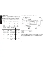
170FAVT - WIRING DIAGRAM
If any original wiring as supplied by the heater must be replaced, it must be
replaced with type AWG 105° C wire or its equivalent except as indicated
(*type SF2-200, **SGI 250° C).
COLOR CODE
B - BLACK
R - RED
L - BLUE
W - WHITE
G - GREEN
O - ORANGE


