English
12
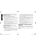
FOLLOW THESE STEPS WHEN THE BATTERY HAS BEEN
REMOVED FROM A VEHICLE
WARNING
– A spark near the battery may cause an explosion. To
reduce risk of a spark near the battery:
Through Bank 1 Using the Built-in Battery Clamps:
1. Check polarity of the battery posts. The positive post (marked
POS, P, +) usually has a larger diameter than the negative battery
post (marked NEG, N, –).
2. Attach a 24-inch (minimum length) AWG #6 insulated battery cable
to the negative battery post (marked NEG, N, –).
3. Connect the positive (red) clamp to the positive battery post (red
or marked POS, P, +).
4. Stand as far back from the battery as possible, and do not face
the battery when making final connection.
5. Carefully connect the negative (black) clamp to the free end of the
battery cable connected to the negative terminal.
6. When disconnecting the charger, always do so in reverse sequence
of connecting procedure and break first connection while as far
away from battery as practical.
Through Bank 2 Using the Clamp Cable Set with O-ring
Connectors (sold separately):
The terminal posts (connections) for Bank 2 are located on the front
of the battery charger. Refer to the Fig. 1.
WARNING
– To
prevent risk of injury and explosion, only connect
manufacturer-supplied clamp cable sets.
1. Turn the red plastic cap on the battery charger’s Bank 2 positive
(+) terminal post (counterclockwise) and remove. Attach the O-ring
at the end of the red clamp cable onto the battery charger’s Bank
2 positive (+) terminal post. Replace the cap and turn clockwise
to secure. Do not over-tighten.
2. Turn the black plastic cap on the battery charger’s Bank 2 negative
(–) terminal post (counterclockwise) and remove. Attach the O-ring
at the end of the black clamp cable onto the battery charger’s Bank
2 negative (–) terminal post. Replace the cap and turn clockwise
to secure. Do not over-tighten.
3. Check the polarity of battery posts. The positive (POS, P, +) battery
post usually has larger diameter than the negative (NEG, N, –) post.
4. Attach a 24-inch (minimum length) AWG #6 insulated battery cable
to the negative battery post (marked NEG, N, –).
5. Connect the positive (red) clamp to the positive battery post (red
or marked POS, P, +).
6. Stand as far back from the battery as possible, and do not face
battery when making final connection.
7. Carefully connect the negative (black) clamp to the free end of the
battery cable connected to the negative terminal.
8. When disconnecting charger, always do so in reverse sequence
of connecting procedure and break the first connection while as
far away from battery as practical.
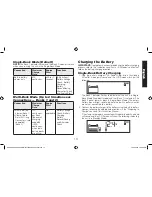
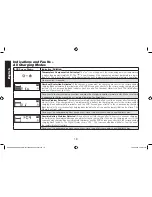
Single-Bank and Multi-Bank Mode
Selection
This battery charger can perform operations utilizing either or both
charging Banks, allowing dual tasks to be performed simultaneously.
Refer to the following tables to select the appropriate Mode for your
application.
NOTE:
The Engine Start function is only available on Bank 1 in Single-
Bank Mode.
DXAEC80_DXAEC80CA_ManualENFRSP_082616.indd 12
10/19/2016 3:58:06 PM

