background image

6

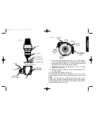
For finest finish, turn feed knob one more calibration and grind
bit. Without touching feed knob, turn sleeve 180° clockwise (step
6 on page 5) and grind first lip until sparking stops.

3. Turn motor “OFF.” Raise swinghead to loading position and

remove bit. 

CAUTION: Tip of bit may be hot.

Wheel Dressing 

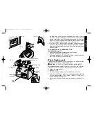
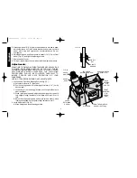
(Figs. 20, 21, 22)

The special grinding wheel included with your D

E

WALT drill bit

sharpener is ready to sharpen your bits. When the sharpening
surface becomes worn and uneven, it’s time to dress the wheel.
Follow these steps:

IMPORTANT: See instructions for shifting from “S” (sharpen) to

“D” (dress) under “Shifting selector to sharpen bits or dress wheel.”
After you have taken the necessary steps, proceed to:
1. Press latch and move swinghead to loading position.
2. Take diamond dressing tool which is kept in the spring-clip in back

of the sharpener. Remove protective sleeve. Position the dust
shield as shown below. Position diamond dresser in chuck, with
diamond tip 1/16" (1.6 mm) beyond locator as illustrated. Tighten
chuck jaws by turning chuck nut clock-wise. Slide dust shield up
against face of chuck to prevent grit and dust from fouling chuck.
(Fig. 20 & 21)

3. Move swinghead downward until latch engages. Adjust feed knob

clockwise until diamond tip almost touches sharpening surface of
the grinding wheel. 

4. With SLIGHT PRESSURE, push swinghead back and away from

eyeshield until it stops.

5. Turn motor “ON.” Maintain light pressure, away from the

eyeshield, on the swinghead. Move the diamond back and forth
across the wheel by turning the dress knob clockwise and
counterclockwise. Feed the diamond into the wheel by turning

English

FIG. 17

FIG. 18

FIG. 19

SLEEVE

TURN SLEEVE 180°

 DW751/385103  5/2/02  12:51 PM  Page 6

Содержание DW751

Страница 1: ...DEWALT Industrial Tool Co 701 East Joppa Road Baltimore MD 21286 Printed in U S A JAN98 CD 1 Form No 385103 DW751 Copyright 1998 DW751 385103 5 2 02 12 51 PM Page 2 ...

Страница 2: ...Drill Bit Sharpener Affûte foret Afilador de brocas INSTRUCTIVO DE OPERACIÓN CENTROS DE SERVICIO Y PÓLIZA DE GARANTÍA ADVERTENCIA LÉASE ESTE INSTRUCTIVO ANTES DE USAR EL PRODUCTO Questions See us on the World Wide Web at www dewalt com DW751 385103 5 2 02 12 51 PM Page 3 ...

Страница 3: ...shown in sketch D An adapter sketches B and C is available for connecting sketch A type plugs to 2 prong receptacles The green colored rigid ear lug or the like extending from the adapter must be connected to a permanent ground such as a properly grounded outlet box No adapter is available for a plug as shown in sketch D ADAPTER SHOWN IN FIGURES B and C IS NOT FOR USE IN CANADA English IF YOU HAVE...

Страница 4: ...ce at all times MAINTAIN TOOLS WITH CARE Keep tools sharp and clean for better and safer performance Follow instructions for lubricating and changing accessories Inspect tool cords periodically and if damaged have repaired by authorized service facility Inspect extension cords periodically and replace if damaged Keep handles dry clean and free from oil and grease DISCONNECT OR LOCK OFF TOOLS when ...

Страница 5: ...umping or dropping DO NOT use a grinding wheel that has been dropped Before using inspect each grinding wheel for cracks or flaws and if these are evident discard the wheel Always use guards and eye shields Keep the eye shield mounted in proper positions Do not overtighten wheel nut Before mounting a new wheel be sure that it is marked with an R P M that is the same as or higher than the no load s...

Страница 6: ... side without removing the bit from the chuck The Swinghead lets you move the bit across the grinding wheel at the correct angle repeatedly The Chuck holds bit in position during sharpening operation The Locator guides positioning of drill bit so that sharpening will be correct and accurate Shifting Selector Sharpen Bits or Dress Wheel Figs 6 7 8 9 10 When you are ready to sharpen bits the selecto...

Страница 7: ... Adjustments section of this manual 1 The swinghead has two indexing positions 180 apart Rotate sleeve to make sure it is seated with locator in top position Make sure selector switch on top of the tool is in the S sharpen position Fig 11 2 Press latch toward swinghead and move swinghead toward loading position Fig 12 3 Open chuck jaws by turning chuck nut counter clockwise Fig 13 4 Insert smaller...

Страница 8: ... to the wheel Each calibration mark between numbers moves the bit 1 1 4 thousandths 4 Moving the feed knob clockwise one calibration mark at a time continue to rock the swinghead across the wheel until the edge of the bit is about 1 32 8 mm from the end of the locator BE CAREFUL NOT TO GRIND LOCATOR IMPORTANT Make a note of the final feed knob setting because you ll need it when you sharpen the se...

Страница 9: ...2 Take diamond dressing tool which is kept in the spring clip in back of the sharpener Remove protective sleeve Position the dust shield as shown below Position diamond dresser in chuck with diamond tip 1 16 1 6 mm beyond locator as illustrated Tighten chuck jaws by turning chuck nut clock wise Slide dust shield up against face of chuck to prevent grit and dust from fouling chuck Fig 20 21 3 Move ...

Страница 10: ... mark Wheel Replacement Replace the grinding wheel when it has been worn down from the original 5 127 mm to 4 102 mm diameter CAUTION REPLACE A CRACKED WHEEL IMMEDIATELY For replacement use only a DEWALT 5 127 mm x 3 4 19 mm wheel DW7510 This wheel is designed specifically for this tool To replace the grinding wheel 1 UNPLUG TOOL 2 Remove 3 screws holding wheel cover and remove cover 3 Hold wheel ...

Страница 11: ...SHARPENER UNPLUG TOOL BEFORE MAKING ANY ADJUSTMENTS 1 Looseness in Pivot Rod Bearing System Fig 25 A Set selector lever to S Sharpen B Position swinghead with locator approximately 1 8 3 mm above wheel C Loosen both front bearing gib screws until slight side play in pivot is evident D While rocking swinghead adjust back bearing gib screw until very slight pivoting resistance is felt Back off screw...

Страница 12: ...between guards and wheel to 1 16 1 6 mm by means of adjusting screws as shown Maintain clearance as wheel wears NOTE This sharpener is completely adjusted at the factory However due to rough handling that might occur during shipment slight readjustments may be necessary Please take a few minutes to check the adjustments of your unit 9 English FIG 26 CHUCK FELT SEAL V SHAPE UP DETENT SPRING U SHAPE...

Страница 13: ...ast Slow down feed rate A Looseness in pivot rod bearing system see adjustments B Wheel needs dressing C Feed at slower rate D Slow down speed of rocking motion A Bent bit B Looseness in pivot rod bearings follow adjustments C Unequal hand pressure on swinghead while sharpening Latch set screw needs adjustment Gib screws adjusted too tight Place a 1 8 3 mm bit in chuck and bend locator until the t...

Страница 14: ...nding wheel with 3 bevel on sharpening surface 2 Diamond wheel dresser 3 Extra locator Accessories Recommended accessories for use with your tool are available at extra cost from your distributor or authorized service center Replacement 5 127 mm x 3 4 19 mm Grinding Wheel DW7510 Replacement Diamond Dresser DW 7511 Bit Locator DW 7512 CAUTION The use of any non recommended accessory may be hazardou...

Страница 15: ...est doté d une fiche semblable à celle illustrée à la figure D On peut se procurer un adaptateur fig B et C pour brancher une fiche semblable à celle de la figure A dans des prises à deux orifices Il faut alors relier la tige la cosse ou le dispositif similaire de couleur verte à une mise à la terre permanente comme une prise bien mise à la terre Il n y a pas d adaptateur pour Français SHARPENING ...

Страница 16: ...e cordon ni tirer sur ce dernier pour le débrancher de la prise Éloigner le cordon des sources de chaleur des flaques d huile et des arêtes tranchantes ASSUJETTIR LA PIÈCE Immobiliser la pièce à l aide de brides ou d un étau On peut alors se servir des deux mains pour faire fonctionner l outil ce qui est plus sûr NE PAS DÉPASSER SA PORTÉE Toujours demeurer dans une position stable et garder son éq...

Страница 17: ...et à droite de 3 mm 1 8 po à 13 mm 1 2 po de diamètre NE PAS tenter d affûter des forets au carbure ou au cobalt Puisqu il faut respecter les consignes afin d obtenir des résultats satisfaisants lire attentivement les directives relatives au fonctionnement et par un surcroît de protection accorder une attention particulière aux mesures de sécurité Porter des lunettes de sécurité Utiliser la meule ...

Страница 18: ...trouvent sur la face inférieure de l affûte foret fig 5 Serrer les écrous sur les boulons uniformément en exerçant une force modérée Éviter de trop serrer Principales composantes de l affûte foret MISE EN GARDE Prendre garde connaître et respecter toutes les MESURES DE SÉCURITÉ S assurer que le positionneur est loin de la meule avant de démarrer l outil Exercer une pression légère et imprimer un m...

Страница 19: ...sition S pour affûter La position D pour décrasser sert pour décrasser les meules IMPORTANT Lorsque le changement de mode de fonctionnement est mal fait cela présente des risques de dommage à l outil et cela peut même le rendre inopérant Les méthodes de changement appropriées sont illustrées PASSAGE DU MODE S AFFÛTE FORET AU MODE D DÉCRASSE MEULE NOTE Exécuter l étape 1 avant de passer à l étape 2...

Страница 20: ...nché avec le positionneur dans l emplacement supérieur S assurer que le sélecteur du dessus de l outil se trouve à la position S affûtage fig 11 2 Enfoncer le loquet vers la tête pivotante et déplacer la tête vers la position de chargement fig 12 3 Ouvrir les mâchoires du mandrin en faisant tourner l écrou du mandrin dans le sens antihoraire fig 13 4 Insérer les forets de petits diamètres au delà ...

Страница 21: ...ER IMPORTANT Lorsqu on avance le bouton d alimentation d un cran de 2 à 3 par exemple le foret se déplace de 5 millièmes de pouce vers la meule Chaque degré marque entre les chiffres correspond à un déplacement de 1 1 4 millième du foret 4 Tout en déplaçant le bouton d alimentation d un cran marque à la fois continuer de faire basculer la tête pivotante le long de la meule jusqu à ce que l arête d...

Страница 22: ...s pour passer du mode S affûte foret au mode D décrasse meule sous la rubrique relative au sélecteur Après avoir respecté les consignes appropriées faire ce qui suit 1 Enfoncer le loquet et déplacer la tête à la position de chargement 2 Prendre le décrasse meule diamant qui se trouve dans une pince à ressort à l arrière de l affûte foret En retirer le manchon protecteur Placer l écran antipoussièr...

Страница 23: ...a tête pivotante près de l écran protecteur 3 Déplacer le sélecteur à la position S NE PAS FORCER Lorsque le sélecteur ne s enfonce pas en place vérifier la position de la marque du bouton du décrasse meule Remplacement de la meule Il faut remplacer la meule lorsqu elle passe de son diamètre original de 127 mm 5 po à un diamètre de 102 mm 4 po MISE EN GARDE REMPLACER IMMÉDIATEMENT UNE MEULE CRAQUÉ...

Страница 24: ...a rotation 2 Réglage du loquet fig 26 A Déplacer la tête pivotante à la position d affûtage B Desserrer la vis de pression du mandrin à l aide d une clé hexagonale de 3 mm 1 8 po jusqu à ce que le mandrin et le ressort de détente puissent être enlevés de la tête pivotante C Régler la vis de pression du loquet avec une clé hexagonale de 1 6 mm 1 16 po de sorte à verrouiller fermement la tête pivota...

Страница 25: ...VIS DE PRESSION DU MANDRIN FICHE VIS DE PRESSION DU LOQUET VIS DE SERRAGE DE LA TÊTE PIVOTANTE ENFONCER LOQUET FIG 27 FIG 26 VIS DE RÉGLAGE DE LA BANDE DE PROTECTION MEULE VIS DE RÉGLAGE DU PROTÈGE DOIGTS PROTÈGE DOIGTS BANDE DE PROTECTION 1 6 mm 1 16 po 1 6 mm 1 16 po DW751 385103 5 2 02 12 51 PM Page 22 ...

Страница 26: ... ne restant pas verrouillée en position d affûte foret ou de décrasse meule 8 Tête pivotante difficile à faire basculer 9 Positionneur plié 10 Outil inhabituellement chaud SOLUTION Le foret n a pas été affûté suffisamment près du positionneur ou il était mal placé Voir l étape 6 des préparatifs en vue de l affûtage L arête du positionneur ne reposait pas à plat contre la goujure Voir l étape 6 des...

Страница 27: ...s industriels de service intensif DEWALT sont garantis pendant un an à partir de la date d achat Toute pièce d un outil DEWALT qui s avérait défectueuse en raison d un vice de matière ou de fabrication sera réparée ou remplacée sans frais Pour obtenir de plus amples renseignements sur les réparations couvertes par la garantie composer le 1 800 4 DEWALT 800 433 9258 La ga rantie ne couvre pas les a...

Страница 28: ...IONES Instrucciones de aterrizaje Esta herramienta debe conectarse a tierra para proteger al operador de choques eléctricos Esta unidad está equipada con un cordón eléctrico de tres hilos y una clavija para aterrizaje de tres patas para conectarse a la toma de corriente adecuada El conductor verde o verde y amarillo es el cable de tierra Nunca conecte el cable verde o verde y amarillo a una termin...

Страница 29: ...rese de que tenga el calibre suficiente para soportar la corriente necesaria para su producto Una extensión con calibre menor al necesario Español Instrucciones de seguridad para todas las herramientas CONSERVE LIMPIA LA ZONA DE TRABAJO Las superficies y los bancos con objetos acumulados en desorden propician los accidentes OTORGUE PRIORIDAD AL AMBIENTE DE TRABAJO No deje las herramientas eléctric...

Страница 30: ...4 12 No Recomendado diga otra cosa en el manual del usuario Haga que se cambien los interruptores dañados en un centro de servicio autorizado No emplee ninguna herramienta que tenga inutilizado o estropeado el interruptor Reglas adicionales de seguridad para el afilador de brocas ADVERTENCIA Esta herramienta profesional está diseñada para afilar de manera rápida y precisa brocas derechas de doble ...

Страница 31: ...5 16 8 mm en el banco de trabajo como se muestra en la figura 4 Inserte dos tornillos de carro de 1 4 6 mm de diámetro deslice el afilador sobre las cabezas de los tornillos y acomode las cabezas en las aberturas que se han provisto para este efecto en la parte inferior de la herramienta Fig 5 Apriete las tuercas en los tornillos de manera uniforme con fuerza moderada No se exceda al apretar Parte...

Страница 32: ...contra la estría El 29 Español Utilice poca presión y haga un movimiento uniforme al balancear la cabeza móvil al esmerilar Cuando cambie del modo de AFILADO DE BROCAS al de DESBASTADO y vice versa tenga cuidado de seguir las instrucciones Reemplace inmediatamente una piedra de esmeril cuarteada Nunca desarme la herramienta ni trate de hacer arreglos en las conexiones eléctricas El selector de mod...

Страница 33: ...cia atrás al mismo tiempo que gira la perilla de alimentación en el sentido de las manecillas del reloj NO HAGA DEMASIADA PRESION CON LA MANO AL BALANCEAR LA CABEZA INCLINABLE IMPORTANTE Al avanzar un número en la perilla de alimentación p e de 2 a 3 se acerca la broca 5 milésimos de pulgada a la piedra Cada marca de calibración entre los números mueve la broca un milésimo y un cuarto 4 Moviendo l...

Страница 34: ...sentido de las manecillas del reloj paso 6 en esta página y esmerile el primer borde hasta que deje de haber chispas 3 APAGUE el motor Levante la cabeza inclinable a la posición de carga y saque la broca PRECAUCIÓN La punta de la broca puede estar caliente Desbaste de la piedra Figs 20 21 22 La piedra de esmeril especial que se incluye con su afilador de brocas DEWALT está lista para afilar Cuando...

Страница 35: ...A EL MOTOR Conserve poca presión en la cabeza inclinable lejos del protector ocular Mueva el desbastador de diamante hacia adelante y hacia atrás a través del disco girando la perilla de desbaste en el sentido de las manecillas del reloj y al revés Alimente el diamante en el disco girando la perilla en el sentido de las manecillas del reloj una calibración a la vez Un movimiento suave uniforme a l...

Страница 36: ...a y la roldana de sujeción CUERDA IZQUIERDA GIRELA EN EL SENTIDO DE LAS MANECILLAS DEL RELOJ Quite la piedra 4 Mueva la banda de la guarda y la guarda a la posición más alta posible Fig 27 5 Coloque la piedra nueva Fig 24 Note que la piedra está marcada para señalar que lado queda hacia fuera con la roldana de sujeción y la tuerca de la flecha Sujete la piedra con un trapo y apriete la tuerca en s...

Страница 37: ...cabeza inclinable ajuste el tornillo de cuña del balero trasero hasta sentir una muy ligera resistencia al giro Afloje el tornillo de 1 8 a 1 4 de vuelta E Ajuste los tornillos de cuña superior e inferior del balero frontal de manera uniforme al tiempo que balancea la cabeza inclinable hasta sentir una muy ligera resistencia al giro 2 Ajuste del cerrojo Fig 26 A Mueva la cabeza inclinable a la pos...

Страница 38: ...vo el muelle note la orientación de las proyecciones en U y en V y el portabrocas E Apriete el prisionero que manera que el portabrocas quede acomodado en la cabeza inclinable pero pueda girarse con facilidad 3 Guarda y banda de la guarda Fig 27 Ajuste la abertura entre las guardas y la piedra a 1 6 mm 1 16 por medio de los tornillos de ajuste como se muestra Conserve esta luz con el desgaste de l...

Страница 39: ...n de afilado o desbaste 8 Difícil de girar la cabeza inclinable hacia adelante y hacia atrás 9 Buscador doblado REMEDIO La broca no se esmeriló lo suficientemente cerca al buscador o se posicionó incorrectamente consulte el paso 6 bajo Prepárese para afilar El borde del buscador no está plano contra la estría Consulte el paso 6 bajo Prepárese para afilar O la broca estaba demasiado cerca del busca...

Страница 40: ...ramienta industrial dewalt sencillamente devuélvala a los vendedores participantes durante los primeros 30 días después de la fecha de compra para que le efectúen un reembolso completo Por favor regrese la unidad completa con el transporte pagado Se puede requerir prueba de compra 37 Español 10 La unidad se calienta mucho portabrocas y doble el buscador hasta que la punta quede directamente sobre ...

Страница 41: ...ctricas o llame al 326 7100 PARA REPARACION Y SERVICIO DE SUS HERRAMIENTAS ELECTRICAS FAVOR DE DIRIGIRSE AL CENTRO DE SERVICIO MAS CERCANO CULIACAN Av Nicolas Bravo 1063 Sur 91 671 242 10 GAUDALAJARA Av La Paz 1779 91 3 826 69 78 MEXICO Eje Lázaro Cárdenas No 18 Local D Col Obrera 588 9377 MERIDA Calle 63 459 A 91 99 23 54 90 MONTERREY Av Francisco I Madero Pte 1820 A 91 83 72 11 25 PUEBLA 17 Nort...

Страница 42: ...ta póliza sellada por el establecimiento comercial donde se adquirió el producto de no contar con ésta bastará la factura de compra EXCEPCIONES Esta garantía no será válida en los siguientes casos Cuando el producto se hubiese utilizado en condiciones distintas a las normales Cuando el producto no hubiese sido operado de acuerdo con el instructivo de uso que se acompaña Cuando el producto hubiese ...

Отзывы: