background image

Synchronous serial interface 

Deutschmann Automation GmbH & Co. KG

24

Instruction manual UNIGATE

®

 IC - PROFINET 1Port V. 3.4

27.11.20

5

Synchronous serial interface

The synchronous serial interface of the UNIGATE

®

 IC is used to connect clocked shift registers 

or components that have a Serial Peripheral Interface (SPI).

It allows 

the expansion of the IC for digital inputs and outputs (for example for driving LEDS or for rea-
ding switch positions)

communicate with microcontrollers or

the control of DA and AD converters.

Connection examples are give in chapter 3.
By using the synchronous serial interface can realize products that can work without another 
microcontroller (stand-alone mode). Examples are sensor products or digital IO modules

5.1

 Shift register operation

Before the interface can be used, it has to be initialized by setting various Script parameters. 
(see chapter 5.1.1)
The parameters „

ShiftRegisterInputType

“ and „

ShiftRegisterOutputType

“ allow the 

use of different shift register types, which differ in the polarity of the shift register signals. To use


the shift register types 74595 and 74165, for example, the values „

RiseClk_RiseLoad

“ and 

RiseClk_LowLoad

“ can be set.

The shift register width is set by the parameter „

ShiftRegisterInputBitLength

“ and 

ShiftRegisterOutputBitLength

“ The maximum width is 256 bits.

The data exchange with the connected shift registers ensues with the commands „

WriteShif-

tRegister

“, „

ReadShiftRegister

“ or bidirectional with the command „

ShiftRegisterDa-

taExchange

“. The clock rate is approx. 45 kHz.

Further information on the commands and parameter values can be found in the Help section of 
the Protocol Developer Software. On request, the Deutschmann Script language can be comple-
mented by additional parameter values in order to support other types of shift registers.

5.1.1

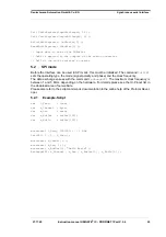
Example-Script

Note: The script example refers to the circuit example in chapter 3.5.

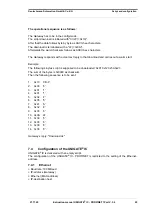
var InBuffer: Buffer[2];

var OutBuffer: Buffer[2];

MoveConst( OutBuffer[0], #0x58#0x21 );

Set( ShiftRegisterInputType, RiseClock_FallLoad );

Set( ShiftRegisterOutputType, RiseClock_RiseLoad );

Содержание UNIGATE IC-PROFINET

Страница 1: ...Instruction Manual Universal Fieldbus Gateway UNIGATE IC PROFINET 1Port Deutschmann Automation GmbH Co KG www deutschmann com wiki deutschmann de...

Страница 2: ...Manual Art No V3641E...

Страница 3: ...13 3 2 8 LED LINKACT 13 3 2 9 Error LED 14 3 2 10 State LED 14 3 2 11 Config Mode 14 3 2 12 DbgTX DbgRx 14 3 2 13 TE 14 3 2 14 TX RX 14 3 3 Software 15 3 4 Basic line of proceeding 15 3 5 Connection...

Страница 4: ...P Server 33 9 1 Script update via FTP 33 9 2 System configuration update via FTP 33 10 WEB Server 34 10 1 Server Side Includes SSI 34 10 2 HTML Forms 35 10 3 Example 35 11 File System 36 12 PROFINET 3...

Страница 5: ...pter RS232 43 16 2 Adapter RS485 43 16 3 FirmwareDownloadTool FDT 43 16 4 Protocol Developer 43 16 5 Developerkit UNIGATE IC AB IC 43 16 5 1 Developerboard UNIGATE IC AB 43 16 5 2 Quick start 44 17 Ap...

Страница 6: ...Deutschmann Automation GmbH Co KG 6 UNIGATE Fieldbus Gateway UNIGATE IC PROFINET 1Port V 3 4 27 11 20...

Страница 7: ...in the publication is however reviewed regularly Necessary amendments are incorporated in the following editions We would be pleased to receive any improvement proposals which you may have Copyright C...

Страница 8: ...Deutschmann Automation GmbH Co KG 8 Instruction manual UNIGATE IC PROFINET 1Port V 3 4 27 11 20...

Страница 9: ...also differ ent fieldbusses can easily be integrated Through the flexible firmware of UNIGATE IC no software changes are required on the side of the customer Since 1997 Deutschmann Automation has exp...

Страница 10: ...th a serial asynchronous interface with a TTL level It is directly connected with the TTL interface of the UNIGATE IC For more information on this serial interface see chapter 4 on page 23 2 5 The syn...

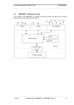
Страница 11: ...C PROFINET 1Port V 3 4 11 Deutschmann Automation GmbH Co KG The UNIGATE IC 2 7 UNIGATE IC hardware survey The hardware of the UNIGATE IC consists of some few standard components The picture below show...

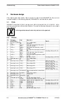
Страница 12: ...clock pulse signal for synchronous serial interface 8 INReset Reset in reset input of the IC internally pulled up with 100 k 9 connected to pin 1 Vcc 3 3V voltage supply 10 12 nc nc no pin 13 accordi...

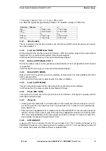
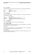
Страница 13: ...ignal The most significant bit of the data is expected first In SPI mode this Pin serves as data transfer from Slave to Master 3 2 5 Load In SPI MOSI This pin is the strobe signal for the input data o...

Страница 14: ...see chapter 13 Flash 1 Hz Bus started waiting for connection configuration mode On connected 3 2 11 Config Mode If the pin has the level GND then the IC starts in the configuration mode 3 2 12 DbgTX D...

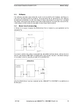
Страница 15: ...pt commands of the Protocol Developer see the instruction manual Proto col Developer and the online documentation concerning script commands 3 4 Basic line of proceeding In theory it is enough to repl...

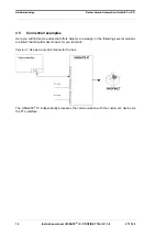
Страница 16: ...ction examples Here you will find some advise that offers help for a re design In the following several versions are listed that should make it easier for you to decide Version 1 Use as a pure link mo...

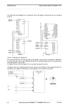
Страница 17: ...re only the synchronous serial interface is used the asynchronous serial interface is basically of no account If you want to program the script in your completed application then the use of a connecto...

Страница 18: ...nchronous and the asynchronous interface as well can be operated by UNIGATE IC at the same time Here the possibility results that an existing application can be extended by additional digital or analo...

Страница 19: ...dwaredesign 3 6 Layout examples When connecting the UG IC and the RJ45 connector it is important to make sure the signal lines RD RD resp TD TD run as short as possible paral lel and equal in length B...

Страница 20: ...4 27 11 20 The 74HCT595 used in this example has an undefined on position but therefor can set the outputs to the tri state condition via the OutEnable Pin 13 If it is more important to have a define...

Страница 21: ...ged in the socket pull an isolated wire over the IC and solder it on the carrier board at the specified holes Fasten the UNIGATE IC with a wire or a tie wrap on the socket Manual soldering directly on...

Страница 22: ...imes etc with RJ45 connectors alone it is probably understandable In General RJ45 connectors and the external or built in Ethernet transformer must meet the fol lowing properties Required parameters f...

Страница 23: ...mation this protocol as well or a Script after an adaptation can be processed by the IC Anyway the IC will take over the communication with the fieldbus independently 4 2 Initialization of the serial...

Страница 24: ...sterOutputType allow the use of different shift register types which differ in the polarity of the shift register signals To use the shift register types 74595 and 74165 for example the values RiseClk...

Страница 25: ...I sets the operating type the mode signal polarity and phase and the clock frequency The data exchange ensues with the command ExchangeSPI The maximum clock frequency is between 1 and 5 MHz depending...

Страница 26: ...or the Debug interface The Debug interface is always operating with 9600 baud no parity 8 data bit 1 stop bit It is not possible to change this parameter in the Protocol Developer Please consider the...

Страница 27: ...this mode it is possible to change the UNIGATE IC s settings of the standard software or to write a new script in the UNIGATE IC It shows its start in the con figuration mode by issuing a status mess...

Страница 28: ...LF 0x0A Send checksum as HEX string e g 0xB33F B33F Wait for reception of Restart in output from device Yes No Send rst 96 bytes of DCS le as 192 byte HEX string e g 0x2E 2E Wait for reception of 0x2...

Страница 29: ...eply to that download and carries out a warm start Example The following 4 bytes script is supposed to be downloaded 0x01 0x12 0x5A 0x23 The sum of the bytes is 0x0090 as checksum Then the following s...

Страница 30: ...on GmbH Co KG 30 Instruction manual UNIGATE IC PROFINET 1Port V 3 4 27 11 20 7 4 2 RS232 RS485 RS422 RS ype RS232 Start bit 1 Data bits 8 Stop bit 1 Parity None Baud rate 9600 Baud Default setting Thi...

Страница 31: ...roup of commands deals with the communication in general This group s commands enable the gate way to send and receive data on the serial side as well as on the bus side 8 4 Independence of buses Basi...

Страница 32: ...provided that it is not the first start Typical for Windows script commands can be added by means of the mouse or the keyboard As far as defined and required for the corresponding command the dialog t...

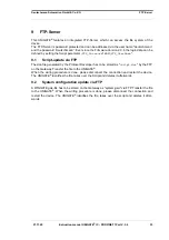
Страница 33: ...ame 9 1 Script update via FTP The dcs file generated by the Protocol Developer has to be stored as script dcs by the FTP on the Gateway Transfer the file to the UNIGATE When the writing procedure is d...

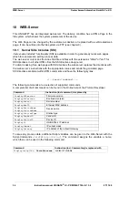
Страница 34: ...server s instructions with the appropriate values and sends the generated page SSI directives are listed within HTML comments and have the following syntax exec command The following commands are a se...

Страница 35: ...ample input forms for process values can be realized The script command SetHTMLInput String assigns a name to a script variable which then can be used in the HTML form 10 3 Example The interaction bet...

Страница 36: ...utschmann css down gif favicon ico h4_pre gif header_schatten jpg headline jpg index html line gif profinet gif rnavmain_bg gif ssi html teaser_header jp device web site Please note that files can not...

Страница 37: ...e The device name is assigned via the configuration software of the Gateway Alternatively the device name can be changed via the FTP file devname txt or via Script Accordingly to the PROFINET specific...

Страница 38: ...t termination of the startup phase the data exchange with external devices will take place 12 7 Literature We recommend the book Der Schnelleinstieg in PROFINET author M Popp and K Weber to help you q...

Страница 39: ...ation purposes and are then automatically reset If such warnings occur frequently please inform After Sales Service The system error can be read out via the Script In the configuration mode these disp...

Страница 40: ...ATE IC can be brought to the firmware update mode by the hardware For it the signal BE boot enable has to be pulled to the potential GND during the Power up process 14 4 Note on safety The firmware up...

Страница 41: ...data on UNIGATE IC All measurements in mm 15 1 Mechanics of the UNIGATE IC 15 1 1 General dimensions of UNIGATE IC 15 1 2 Dimensions UNIGATE IC PROFINET only The pins of UNIGATE IC PROFINET are arrang...

Страница 42: ...NET side Standard IP address Assigned by the PROFINET IO controller SPS see chapter 12 2 Bus baud rate 100 MBaud UART baud rate Up to 520 Kbaud adjustable via script Supported Ethernet protocols UDP I...

Страница 43: ...FDT The FirmwareDownloadTool is available for download from our homepage it is required for an update of the firmware Condition for it is that a PC can be connected to the serial of the IC The softwa...

Страница 44: ...2 The bus connections according to standard or market standard are available to test the respec tive bus side Optionally Deutschmann Add on packages bus master simulation are available The board conta...

Страница 45: ...N rail module and without housing cover PD Board only without DIN rail module and with housing cover AG Gateway installed in a die cast aluminum housing EG Gateway installed in a stainless steel housi...

Страница 46: ...mbH Co KG 46 Instruction manual UNIGATE IC PROFINET 1Port V 3 4 27 11 20 product PBDPX PROFIBUS DP version X see comparison table UNIGATE IC for the respective product PBDPV0 PROFIBUS DPV0 PBDPV1 PROF...

Страница 47: ...to midday and from 1 pm to 4 pm Friday from 8 am to midday CET Deutschmann Automation GmbH Co KG Carl Zeiss Stra e 8 D 65520 Bad Camberg Germany Central office and sales department 49 6434 9433 0 Tec...

Страница 48: ......

Отзывы: