- 27 -
Controller Panel
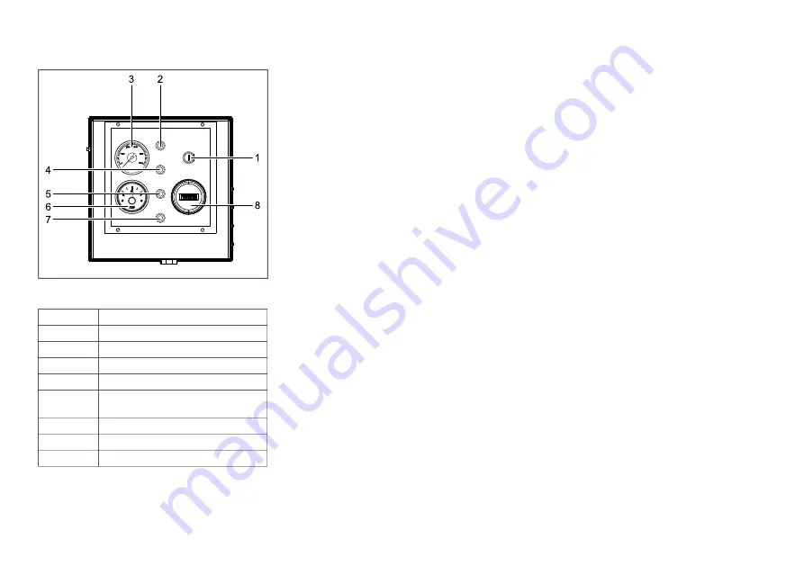
CONTROL PANEL DESCRIPTION
1. The engine ignition key port (1) is used to start the
engine.
2. The fuel level low indicator (2) glows if the fuel
level in the fuel tank is low.
3. The pressure gauge (3) is used to monitor the
outlet pressure of the unit.
4. The battery malfunction indicator (4) glows if the
battery is about to fail. Some situations where this
indicator will glow are when the level of
electrolyte is low, the battery is short, the battery
begins gassing, the battery is overheating etc.
5. The temperature switch at the compressor outlet
port continuously monitors the outlet temperature.
If the outlet temperature exceeds the limiting
conditions (see section Technical specifications,
limitation ), the compressor outlet temperature
high indicator (5) begins to glow.
6. The Fuel gauge (6) helps monitoring the quantity
of fuel filled into the fuel tank. Do not overfill the
fuel tank. Fill fuel within the limits represented on
the fuel gauge (6).
7. The temperature switch at the outlet of the oil
cooler continuously monitors the oil temperature.
If it is higher than the permissible limits, the Oil
temperature high indicator (7) begins to glows.
8. The machine running hours can be tracked on the
running hours meter (8). It can be used to track
hours between required service activities.
STARTING/STOPPING
SAFETY PRECAUTION
1. Before starting the machine, make sure that the
fuel tank is full.
PROCEDURE
1. Insert the ignition key into the ignition key port
(1). Twist the ignition key in the clockwise
direction to start the engine.
2. Run the engine for a few minutes at no-load to
warm up.
3. To shut down the engine, twist the ignition key in
the anti-clockwise direction.
Reference Description
1
Engine ignition key port
2
Fuel level low indicator
3
Pressure gauge
4
Battery malfunction indicator
5
Compressor outlet temperature high
indicator
6
Fuel gauge
7
Oil temperature high indicator
8
Meter for running hours
Содержание DU-190
Страница 1: ...8 Instruction Manual English...
Страница 2: ......
Страница 16: ...16 Main Parts...
Страница 18: ...18 COMPRESSOR REGULATING SYSTEM...
Страница 22: ...22 CONTINUOUS PNEUMATIC REGULATING SYSTEM...
Страница 60: ...60 ELECTRIC SYSTEM Circuit diagram 9829 3801 10...
Страница 61: ...61 Circuit diagram 9829 3801 10...
Страница 62: ...62 ELECTRIC SYSTEM Wire harness 1094 3133 02...
Страница 65: ...65 Maintenance Log Compressor Customer Serial number Service hours Maintenance action Date By initials...
Страница 67: ......
Страница 68: ......


