background image

Getting Started

Connections

Setup

Information

Troubleshooting

ENGLISH

Specifications

Preparations

1


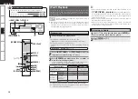
Connect the power cord.

The  power  indicator  lights  red  and  the  power  is  set  to  the 
standby mode.

2


Press 

<ON/STANDBY> 

or 

[POWER ON].


The power indicator flashes green and the power turns on.

b

 Also  press 

INPUT  SELECT

  when  in  standby  mode,  the  power 

turns  on.  In  this  case  the  input  source  is  selected  by  remote 
control unit.

Turning the Power Off

Press 

<ON/STANDBY>

 or 

[POWER OFF]

.

The power is set to the standby mode.

NOTE

Power continues to be supplied to some of the circuitry even when 
the  power  is  in  the  standby  mode.  When  leaving  home  for  long 
periods of time or when traveling, unplug the power cord from the 
power outlet.

Turning the Power On

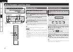
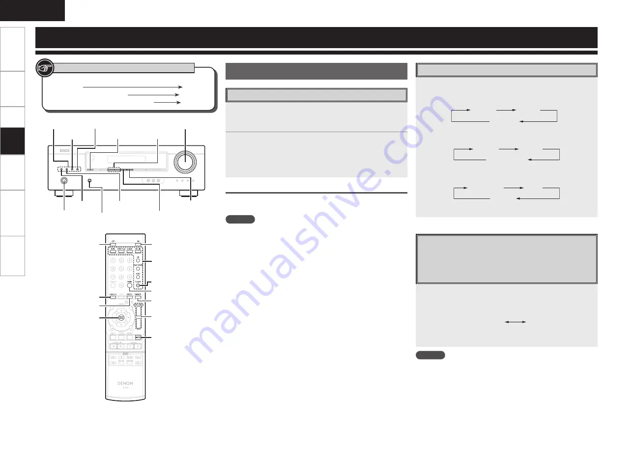
Select the source using 

INPUT SELECT

.

The  input  source  changes  as  follows  each  time  you  press 

<VIDEO>

VCR

DVD

V.AUX

The  input  source  changes  as  follows  each  time  you  press 

<AUDIO>

CD

AUX

CD-R / TAPE

The  input  source  changes  as  follows  each  time  you  press 

<TUNER>

FM MONO

AM

FM ST

Press 

<EXT. IN>

 to select “EXT. IN”.

Switching between Digital Audio Input 

and Analog Audio Input

When  a  single  source  is  connected  by  both  digital  and  analog 
connectors, this enables you to change the audio input method 
with one button. 

Playback

Press 

DIGITAL INPUTS

.

Each time this button is pressed, the corresponding input is selected 
as follows:

VCR  : O(ptical)

DVD  : C(oaxial) 1

A(nalog)

CD   : C(oaxial) 2

z

Displays the connected terminal name.

NOTE

• When TUNER, AUX, CD-R / TAPE, EXT. IN or V.AUX is selected as 

an input source, the analog input is selected automatically.

• When the selected digital input is not connected, the analog input 

is automatically selected.

• The sound from the component connected to the selected digital 

input can be heard regardless of the selected input source.

Selecting the Input Source

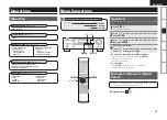
Button located on both the main unit and the remote  
control unit  


BUTTON

Button only on the main unit


<BUTTON>

Button only on the remote control unit


[BUTTON]

Symbols used to indicate buttons in this manual

DIGITAL INPUTS

INPUT SELECT

<ON/STANDBY>

<AUDIO>

<VIDEO>

<TUNING

df

>

MASTER VOLUME

MEMORY/ENTER

STATUS

<TUNER>

<EXT. IN>

d

 f

[MUTE]

[POWER ON]

INPUT SELECT

[POWER OFF]

DIGITAl INPUTS

STATUS

MEMORY/ENTER

[BAND]

TUNER

[DIMMER]

MASTER VOLUME

PHONES jack

Playback

Содержание AVR-390

Страница 1: ...AV SURROUND RECEIVER AVR 390 Owner s Manual Bedienungsanleitung Manuel de l Utilisateur Manual del usuario Инструкция по эксплуатации Instrukcja Obsługi Kullanım Kılavuzu ...

Страница 2: ...y 2004 108 EC СЕРТИФИКАТ СООТВЕТСТВИЯ Мы гарантируем что данный продукт к которому прилагается данный сертификат соответствует требованиям следующих стандартов EN60065 EN55013 EN55020 EN61000 3 2 и EN61000 3 3 Согласно условиям директив 2006 95 EC и 2004 108 EC DEKLARACJA ZGODNOŚCI Deklarujemy z pełną odpowiedzialnością że produkt którego dotyczy niniejsza deklaracja jest zgodny z następującymi no...

Страница 3: ...benzyną oraz rozpuszczalnikiem Böcek ilacı benzen ve tiner gibi maddeleri üniteyle temas ettirmeyiniz Never disassemble or modify the unit in any way Versuchen Sie niemals das Gerät auseinander zu nehmen oder zu verändern Ne jamais démonter ou modifier l appareil d une manière ou d une autre Nunca desarme o modifique el equipo de ninguna manera Никогда не разбирайте и не модифицируйте устройство N...

Страница 4: ... reciclaje de su localidad Cuando se deshaga de la unidad cumpla con las reglas o reglamentos locales Las pilas nunca deberán tirarse ni incinerarse Deberá disponer de ellas siguiendo los reglamentos de su localidad relacionados con los desperdicios químicos Este producto junto con los accesorios empaquetados es el producto aplicable a la directiva RAEE excepto pilas III ПРИМЕЧАНИЕ О ПЕРЕРАБОТКЕ У...

Страница 5: ... of Default Values 15 Power On Level 16 Menu Operations System Setup Surround Modes Tone Control 20 Bass 20 Treble 20 Night Mode 21 Dolby PLg Music 21 Panorama 21 Center Width 21 Dimension 21 Parameter Information 21 n Contents Assign 16 iPod Assign Speaker Configuration 16 Front Speaker 16 Center Speaker 16 Surround Speaker 16 Subwoofer 17 Subwoofer Mode Setup 17 Distance 17 Unit 17 Distance meas...

Страница 6: ...ion dew may form on the operating parts inside the unit causing the unit not to operate properly If this happens let the unit sit for an hour or two with the power turned off and wait until there is little difference in temperature before using the unit Cautions on using mobile phones Using a mobile phone near this unit may result in noise If so move the mobile phone away from this unit when it is...

Страница 7: ...the battery fluid should leak carefully wipe the fluid off the inside of the battery compartment and insert new batteries Remove the batteries from the remote control unit if it will not be in use for long periods When replacing the batteries have the new batteries ready and insert them as quickly as possible 30 30 Approx 7 m Operating Range of the Remote Control Unit Point the remote control unit...

Страница 8: ...3 Q3SETUP button 15 Q4SELECT buttons uio p 15 Q5Display 4 Q6Remote control sensor 3 Q7INPUT SELECT buttons 22 Front Panel y t r e q w qDecoder indicators These light when the respective decoders are operating w DIGITAL input indicator This lights when set to digital input vpage 22 ePRESET indicator This lights when the input source is TUNER rMEMORY indicator This lights when registering preset num...

Страница 9: ... OPTICAL COAXIAL 10 13 w EXT IN connectors 14 eAnalog audio connectors AUDIO 10 13 rPRE OUT connector 8 tFM AM antenna terminals TUNER ANTENNA 14 yVIDEO S VIDEO connectors 11 13 uSpeaker terminals SPEAKERS 8 iPower cord 14 oCOMPONENT VIDEO connectors 11 13 Q0HDMI connectors 10 13 Q1DOCK CONTROL jack 12 Rear Panel Getting Started ...

Страница 10: ...D INPUTS 22 uSURROUND PARAMETER button 21 iSETUP button 15 oSelect buttons uio p 15 Q0Memory MEMO ENTER button 15 18 24 Q1Channel select button CH SEL 18 Q2NIGHT button 21 Q3STEREO button 19 Q4SURROUND buttons 0 1 19 Q5Input select buttons 22 Q6BAND button 23 Q7STATUS button 21 23 Q8DIMMER button 23 Q9Master volume control buttons 23 W0TONE button 20 W1MUTE button 23 W2SEARCH button 25 26 W3CHANNE...

Страница 11: ...tput Input Input Output Output Input Input Output Cables Used for Connections Select the cables according to the equipment being connected Preparations Connections NOTE Do not plug in the power cord until all connections have been completed When making connections also refer to the operating instructions of the other components Be sure to connect the left and right channels properly left with left...

Страница 12: ...the front speakers to the sides of the monitor or screen and as flush with the screen surface as possible The table below shows a typical speaker configuration for the AVR 390 FRONT CENTER SURROUND SUBWOOFER L R L R 5 1 channels S S S S S S 3 1 channels S S S S 2 1 channels S S S 2 channels S S Speaker Connections w q w q w q w q w q R L L R Speaker Connections Front speakers Center speaker Subwoo...

Страница 13: ...ted Doing so could result in electric shock Protection circuit If the core wires touch the rear panel and the screws etc or the sides touch each other the protection circuit will be activated and the power indicator will flash red at intervals of 0 5 secs If the protection circuit is activated the speaker output is isolated and the power supply goes to the standby state If the power supply is turn...

Страница 14: ...cting to a monitor etc equipped with a DVI D connector connection is possible using an HDMI DVI converter cable but depending on the combination of components in some cases the video signals will not be output When connecting using an HDMI DVI converter adapter the video signals may not be output properly due to poor connections with the connected cable etc NOTE The AVR 390 cannot be controlled fr...

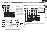
Страница 15: ...tors GFlow of video signals inside the AVR 390H High picture quality playback HDMI connector Component video connectors S Video connector Video connector Monitor HDMI connector Component video connectors S Video connector Video connector Video input terminals Monitor output terminals Carefully check the left L and right R channels and the inputs and outputs and be sure to interconnect correctly Co...

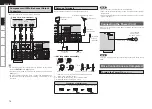
Страница 16: ...iPod settings refer to the control dock for iPod s operating instructions NOTE To playback iPod Video or Photos on a TV monitor connect the TV to the S Video Out terminal of AVR 390 ASD 3N or ASD 3W 4 7 0 3 065 6 0 7 0 065 6 0 7 0 065 015 065 065 0 10 5 7 0 1 13 065 R L R L TV CABLE Tuner Select the terminal to use and connect the device TV Tuner NOTE The audio signal input to the HDMI input conne...

Страница 17: ...ure also to connect these terminals beforehand Video Cassette Recorder Select the terminal to use and connect the device When recording via the AVR 390 the playback device s cable must be of the same type as the cable used to connect the AVR 390 s VCR OUT connector Example DVD IN Video cable VCR OUT Video cable Connect AUDIO and VIDEO VCR OUT terminals when video recording When connecting a video ...

Страница 18: ... wall Mount Installation hole Mount on wall etc Connection of AM antennas 1 Push the lever 2 Insert the conductor 3 Return the lever Wait until all connections have been completed before connecting the power cord Connecting the Power Cord To household power outlet AC 230 V 50 Hz Power cord NOTE Insert the AC plugs securely Incomplete connections could cause noise Component with Multi channel Outpu...

Страница 19: ...anual n To move to a setup item of another category Press ui to select RETURN then press ENTER Returns to the setup menu Perform steps 3 and 4 n To exit setup Press SETUP while the setup menu is displayed The display returns to normal Operations The same operation is possible on the main unit or remote control unit Menu Operations Example of Display of Default Values Parameter vpage 20 21 n Tone C...

Страница 20: ...The display shows CDR z2 The display shows V A Speaker Setup Speaker Configuration Select speaker configuration and size bass reproduction capability Front Speaker Select front speaker size Center Speaker Select center speaker use and size Surround Speaker Select surround speakers use and size Selectable items L S N Selectable items L S N Selectable items L S Display Display Display The display sh...

Страница 21: ... Speaker Configuration Subwoofer is set to Y Play music or a movie source and select the mode offering the strongest bass Select SW if you want the bass signals to always be produced from the subwoofer Display Display Display When Front Speaker is set to S Subwoofer is automatically set to Y If Subwoofer is set to N Front Speaker is automatically set to L When Front Speaker is set to S Center Spea...

Страница 22: ...level with test tone adjust the channel levels either according to the program sources or to suit your tastes For details refer to Adjusting Each Channel Level with Test Tone on page 28 Memorizing the Adjusted Channel Levels You can memorize the adjusted channel levels into preset memory REFERENCE 1 REFERENCE 2 and recall the memorized whenever you want Select the Channel Level This selects the me...

Страница 23: ...e HALL This mode provides the ambience of a concert hall for classical music sources such as orchestral chamber music or an instrumental solo STADIUM This mode provides the expansive sound field to achieve the true stadium effect when watching baseball or soccer games Input Signal Display Dolby Digital EX 6 1 channel sources Dolby Digital 5 1 channel sources DOLBY DIGITAL AUTO SURROUND Dolby Digit...

Страница 24: ...it q Press TONE The display shows the currently set tone mode w Press o p to select the desired tone mode ON OFF e Press ui to select the desired tone BASS TREBLE TONE ON r Press o p to adjust the selected tone as desired b To complete tone adjustment repeat the above steps 3 and 4 b If the tone display disappears start from the step 1 again Variable range 10dB 0dB 10dB Variable range 10dB 0dB 10d...

Страница 25: ...ems ON OFF Display Information The items displayed will differ depending upon the current settings the presence or absence of an input signal or the type of input signal etc For details of the content of the items displayed refer to the page containing an explanation of the settings Information on the main unit s various settings Status and on input signals Audio Input Signal is shown on the displ...

Страница 26: ...N to select EXT IN Switching between Digital Audio Input and Analog Audio Input When a single source is connected by both digital and analog connectors this enables you to change the audio input method with one button Playback Press DIGITAL INPUTS Each time this button is pressed the corresponding input is selected as follows VCR O ptical DVD C oaxial 1 A nalog CD C oaxial 2 z zDisplays the connec...

Страница 27: ...by adjusting the master volume Turning Off the Sound Temporarily Muting NOTE The adjustable range will differ depending upon factors such as the type of input signal and the channel level setting The display shows MIN when you select 0 dB The display shows MAX when you select 80 dB Automatically Presetting FM Stations Auto Preset Up to 30 stations can be preset Auto preset is not possible with AM ...

Страница 28: ...d their displays are as follows NEWS News AFFAIRS Current Affairs INFO Information SPORT Sports EDUCATE Education DRAMA Drama CULTURE Culture SCIENCE Science VARIED Varied POP M Pop Music ROCK M Rock Music EASY M Easy Listening Music LIGHT M Light Classical CLASSICS Serious Classical OTHER M Other Music WEATHER Weather FINANCE Finance CHILDREN Children s programmes SOCIAL Social Affairs RELIGION R...

Страница 29: ... to Program Type PTY 1Press TUNER or BAND to select FM 2Press SEARCH until PTY SRCH appears on the display 3Watching the display press o p to call out the desired program type 4Press ENTER or CHANNEL PTY search begins automatically b If there is no station broadcasting the designated program type with the above operation all the reception bands are searched b The station name is displayed on the d...

Страница 30: ...layed Display mode Browse mode Remote mode Display location Main unit display iPod display Playable files Audio file S S Video file Sz1 Sz2 Active buttons Remote control unit AVR 390 S S iPod A S z1 When using an ASD 3N or ASD 3W control dock for iPod z2 Video may not be output depending on the combination of ASD 1R or ASD 11R and iPod Preparations With the default settings the iPod can be used co...

Страница 31: ...d are replaced with NOTE Depending on the type of iPod and the software version some functions may not operate DENON will accept no responsibility whatsoever for any loss of iPod data Viewing Still Pictures or Videos on the iPod Photo and video data on the iPod can be viewed on the monitor Only for iPod equipped with slideshow or video functions 1Press and hold SEARCH to set the Remote mode 2Watch...

Страница 32: ...ecording on an External Device First connect the device from which you want to record to the AVR 390 Button located on both the main unit and the remote control unit BUTTON Button only on the main unit BUTTON Button only on the remote control unit BUTTON Symbols used to indicate buttons in this manual 1Press TEST b The test tone mode is displayed and will be heard from the speaker of each channel ...

Страница 33: ... 1Turn off the power using ON STANDBY 2While pressing MEMORY ENTER press ON STANDBY 3Release the button when CLEAR is shown on the display 4Press ON STANDBY to complete If CLEAR was not displayed in step 3 repeat operations from step 1 Tuning Interval Change The AM FM tuning interval is factory set to the 9 kHz 50 kHz position If the allocation system of your country is based on the bottom of the ...

Страница 34: ...cessing circuit that lets you play program sources in the surround mode to achieve the same sense of presence as in a movie theater Dolby Pro Logic g Dolby Pro Logic g is a matrix decoding technology developed by Dolby Laboratories Regular music such as that on CDs is encoded into 5 channels to achieve an excellent surround effect The surround channel signals are converted into stereo and full ban...

Страница 35: ...guration setting Surround Modes and Parameters Surround mode Signals and adjustability in the different modes Channel output Front L R Center Surround L R Subwoofer Auto Surround S D D D DOLBY PRO LOGIC g Cinema S D D D DOLBY PRO LOGIC g Music S D D D DOLBY PRO LOGIC S D D D MATRIX S D D D CHURCH S D D D THEATER S D D D HALL S D D D STADIUM S D D D STEREO S A A D EXT IN S S S S Surround mode Signa...

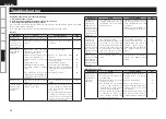
Страница 36: ...the player GGeneralH Troubleshooting Symptom Cause Countermeasure Page Power switches off suddenly while you are using the AVR 390 the power indicator will flash in red at intervals of approximately 2 seconds The protection circuit will be activated depending upon the temperature rise in the internal parts of the unit Please switch off power at once and re apply the power after the body temperatur...

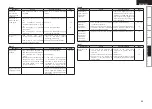
Страница 37: ...ich is connected to component terminals if the monitor is not connected to the component terminals the image will not appear Check the connections 10 13 DVDs cannot be copied on a VCR This is not a malfunction Most movie software includes copy prevention signals and cannot be copied GVideoH Symptom Cause Countermeasure Page HDMI audio signals are not output from speakers The audio signal input to ...

Страница 38: ...NTSC Vp p 75 Ω ohms Frequency response 5 Hz 10 MHz 1 3 dB Color component video connectors Input output level and impedance Y brightness signal 1 Vp p 75 Ω ohms PB CB signal 0 7 Vp p 75 Ω ohms PR CR signal 0 7 Vp p 75 Ω ohms Frequency response 5 Hz 30 MHz 0 3 dB n Tuner section FM AM note µV at 75 Ω ohms 0 dBf 1 x 10 15 W Receiving Range 87 5 MHz 108 0 MHz 522 kHz 1611 kHz 87 5 MHz 107 9 MHz 520 k...

Страница 39: ...Denon Brand Company D M Holdings Inc Printed in China 5411 10272 005D www denon com ...

Отзывы: