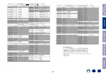
MT41K128M16JT-125:K (DIGITAL : U104, U254)
Block Diagram
Figur
e 7: 96-Ball FBGA – x16 Ball Assignments (T
op V
iew)
1
2
3
4
6
7
8
9
5
A
B
C
D
E
F
G
H
J
K
L
M
N
P
R
T
V
DDQ
V
SSQ
V
DDQ
V
SSQ
V
SS
V
DDQ
V
SSQ
V
REFDQ
NC
ODT
NC
V
SS
V
DD
V
SS
V
DD
V
SS
DQ13
V
DD
DQ11
V
DDQ
V
SSQ
DQ2
DQ6
V
DDQ
V
SS
V
DD
CS#
BA0
A3
A5
A7
RESET#
DQ15
V
SS
DQ9
UDM
DQ0
LDQS
LDQS#
DQ4
RAS#
CAS#
WE#
BA2
A0
A2
A9
A13
DQ12
UDQS#
UDQS
DQ8
LDM
DQ1
V
DD
DQ7
CK
CK#
A10/AP
NC
A12/BC#
A1
A11
NC
V
DDQ
DQ14
DQ10
V
SSQ
V
SSQ
DQ3
V
SS
DQ5
V
SS
V
DD
ZQ
V
REFCA
BA1
A4
A6
A8
V
SS
V
SSQ
V
DDQ
V
DD
V
DDQ
V
SSQ
V
SSQ
V
DDQ
NC
CKE
NC
V
SS
V
DD
V
SS
V
DD
V
SS
Notes:
1.
Ball descriptions listed in T
able 4 (page 20) are listed as “x16.”
2.
A comma separates the configuration; a slash defines a selectable function.
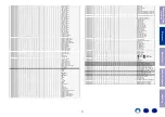
Figure 5: 128 Meg x 16 Functional Block Diagram
Bank 5
Bank 6
Bank 7
Bank 4
Bank 7
Bank 4
Bank 5
Bank 6
13
Row-
address
MUX
Control
logic
Column-
address
counter/
latch
Mode registers
10
Command
decode
A[13:0]
BA[2:0]
14
Address
register
17
(128
x128)
16,384
I/O gating
DM mask logic
Column
decoder
Bank 0
memory
array
(16,384 x 128 x 128)
Bank 0
row-
address
latch
and
decoder
16,384
Sense amplifiers
Bank
control
logic
17
Bank 1
Bank 2
Bank 3
14
7
3
3
Refresh
counter
16
128
128
128
LDQS, LDQS#, UDQS, UDQS#
Column 0, 1, and 2
Columns 0, 1, and 2
ZQCL, ZQCS
To ODT/output drivers
BC4
READ
drivers
DQ[15:0]
READ
FIFO
and
data
MUX
Data
16
BC4 (burst chop)
3
Bank 1
Bank 2
Bank 3
LDM/UDM
CK, CK#
LDQS, LDQS#
UDQS, UDQS#
ZQ CAL
ZQ
RZQ
ODT
CKE
CK, CK#
RAS#
WE#
CAS#
CS#
RESET#
CK, CK#
DLL
DQ[15:0]
(1 . . . 16)
(1 . . . 4)
(1, 2)
SW1
SW2
V
DDQ
/2
BC4
SW1
SW2
V
DDQ
/2
R
TT,nom
R
TT(WR)
SW1
SW2
Column 2
(select upper or
lower nibble for BC4)
Data
interface
WRITE
drivers
and
input
logic
ODT
control
V
SSQ
A12
OTF
OTF
V
DDQ
/2
R
TT,nom
R
TT(WR)
R
TT(WR)
R
TT,nom
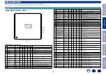
AK4490EQ (DAC : U4001, U4012, U4013, U4014, U4015, U4016, U4017,
U4018)
Pin Function
[AK4490]
MS1648-J-03
2014/11
- 5 -
5.
AK4490EQ 40 +85 C 48pin LQFP (0.5mm pitch)
AKD4490
AK4490
[AK4490]
MS1648-J-03
2014/11
- 6 -
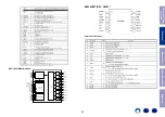
No. Pin Name
I/O
Function
1 NC
-
No internal bonding.
Connect to GND.
2 PDN
I
Power-Down Mode Pin
When at L , the AK4490 is in power-down mode and is held in reset.
The AK4490 must always be reset upon power-up.
3
BICK
I
Audio Serial Data Clock Pin in PCM Mode
DCLK
I
DSD Clock Pin in DSD Mode
BCK
I
Audio Serial Data Clock Pin
4
SDATA
I
Audio Serial Data Input Pin in PCM Mode
DSDL
I
DSD Lch Data Input Pin in DSD Mode
DINL
I
Lch Audio Serial Data Input Pin
5
LRCK
I
L/R Clock Pin in PCM Mode
DSDR
I
DSD Rch Data Input Pin in DSD Mode in Serial Control Mode
DINR
I
Rch Audio Serial Data Input Pin in Serial Control Mode
6
SSLOW
I
Digital filter setting in Parallel Control Mode
WCK
I
Word Clock input pin in Serial Control Mode
7
SMUTE I
Soft Mute Pin in Parallel Control Mode
When this pin is changed to H , soft mute cycle is initiated.
When returning L , the output mute releases.
CSN
I
Chip Select Pin in Serial Control Mode, I2C= L
8
SD
I
Digital filter setting in Parallel Control Mode
CCLK
I
Control Data Clock Pin in Serial Control Mode, I2C= L
SCL
I
Control Data Clock Pin in Serial Control Mode, I2C= H
9
SLOW
I
Digital filter setting in Parallel Control Mode
CDTI
I
Control Data Input Pin in Serial Control Mode, I2C= L
SDA
I/O Control Data Clock Pin in Serial Control Mode, I2C= H
10
DIF0
I
Digital Input Format 0 Pin in PCM Mode
DZFL
O Lch Zero Input Detect Pin in Serial Control Mode
11
DIF1
I
Digital Input Format 1 Pin in PCM Mode
DZFR
O Rch Zero Input Detect Pin in Serial Control Mode
12
DIF2
I
Digital Input Format 2 Pin in PCM Mode
CAD0
I
Chip Address 0 Pin in Serial Control Mode
13 PSN
I
Parallel or Serial Select Pin (Internal pull-up pin)
L : Serial Control Mode, H : Parallel Control Mode
14 I2C
I
I2C mode select pin in Serial mode (Internal pull-down pin)
15 DEM0
I
De-emphasis Enable 0 Pin in Parallel Control Mode (Internal pull-up pin)
Note: All input pins except internal pull-up/down pins must not be left floating.
Before Servicing
This Unit
Electrical
Mechanical
Repair Information
Updating
63

