3. Maintenance and troubleshooting
MERMAID E1100-I
STD00
Page 23 of 54
Step D)
Install the connecting rod cap respecting numbering, and fasten the relevant bolts (lubricating
both the head and the threaded stem with the same oil used for the crankcase) proceeding in
three different steps,see fig. 7:
Torque (Nm) specification:
1. Approaching torque 6 - 8 Nm
2. Pre-fasting torque 25 - 28 Nm
3. Fastening torque 38 Nm
Disassembly / Assembly of the crankshaft without replacing the bearings
After removing the side covers, check the rollers and their races for ware; if all parts are in good
conditions, accurately clean the components with a suitable degreaser and grease them again evenly
using the same oil used in the crankcase.
The same shims can be used again, being careful to fit them under the cover on the sight glass side.
After installing the complete unit (sight glass side shaft + engine side flange), check that the
shaft’s rolling torque - with the connecting rods free – is at least 4 Nm, Max 7 Nm.
Position the two side covers on the crankcase, initially use N°3 screws M6x40 as shown in fig. 6, and
then the fastening screws. The shaft’s rolling torque (with connecting rods coupled) must not exceed
8 Nm.
Содержание MERMAID E1100-I
Страница 33: ...4 Spare parts list MERMAID E1100 I STD00 Page 32 of 54 4 Spare parts list Frame Water Tank Assembly ...
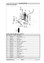
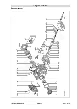
Страница 38: ...4 Spare parts list MERMAID E1100 I STD00 Page 37 of 54 Pump assembly ...
Страница 46: ...4 Spare parts list MERMAID E1100 I STD00 Page 45 of 54 ...
Страница 47: ...4 Spare parts list MERMAID E1100 I STD00 Page 46 of 54 ...
Страница 48: ...4 Spare parts list MERMAID E1100 I STD00 Page 47 of 54 MONRO JET operation and servicing instructions ...
Страница 53: ...5 Wiring Diagram MERMAID E1100 I STD00 Page 52 of 54 5 Wiring Diagram ...


