background image

1. Getting acquainted with your Water Blaster 

MERMAID E1100-I 

STD00 

Page 10 of 54


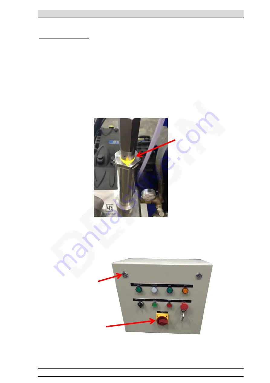
Unauthorized Usage   
 

Unloader/Safety Valve 

Machine’s Safety Valve are factory pre- set. Purpose of the Safety Valve is to prevent the 
machine from over pressure. 
 
Therefore, it is not recommended to adjust the setting on these valves. If setting is required, a 
trained personal must performed the task. Incorrect adjustment(20~30Bar above set pressure) 
to the valve may results machine damage which will cause warranty void.   
 
To prevent unauthorized adjustment to the valves, these valves are applied with tempered 
proof sealant. Once the sealant cracked, it showed that unauthorized activities occur on the 
valves. 


Safety Valve:     


Electrical Components 

 
To prevent unauthorized usage or sabotage, the electrical box & main switch is 
equipped with locks. 


Tempered Proof 
Sealant 

2 Locks System 

Main Switch 
Lock Hole 

Содержание MERMAID E1100-I

Страница 1: ...www densin com USER GUIDE SPARE PARTS MANUAL E1100 I Electrical Powered Heavy Duty Cold Water HIGH PRESSURE CLEANER MERMAID Original Instruction ...

Страница 2: ...utions are not observed Therefore a full understanding of the contents of this instruction manual is required in order to prevent injuries to you objects and persons nearby Safety The following symbols are used in this manual to indicate procedures that if not followed may results in personal injuries or damage to equipment WARNING is used to alert the reader of procedures or practice which if not...

Страница 3: ... hoses and connections tips lances Personal protective equipment must be worn Prior to commencing any water blasting work the area must be barricaded to restrict unauthorized access We recommend to practice to employ 2 operators blasting method The role of the 2nd operator is to attend the pump unit keep close watch on the 1st operator for tiredness Therefore the operators can take turns to operat...

Страница 4: ...idelines 18 3 Maintenance and troubleshooting 19 Maintenance Schedule 19 Machine Do s and Don ts 20 Troubleshooting 21 Service instructions 22 4 Spare parts list 32 Frame Water Tank Assembly 32 Frame Water Tank Assembly spare parts list 33 Motor Pump Assembly 34 Motor Pump Assembly spare parts list 34 Booster Pump Assembly 35 Booster Pump Assembly spare parts list 35 Filter Assembly 36 Filter Asse...

Страница 5: ...s The Water blasters are designed for industrial and for offshore use All pump parts fittings and pipes in contact with water are made of non corrosive materials Together with the ceramic pistons long life seals and stainless steel valves it ensures long life and high durability Specifications Model Moto r Moto r Spee d Working Pressure Flow Capacity Power Supply Dimensi on LxWxH Weight H p k W rp...

Страница 6: ...or use of accessories even many more jobs are to be dealt with Sandblasting Drain cleaning Unpacking Remove the Water Blaster and its accessories from the packing material if any For transport and packing reasons some accessories are supplied disassembled Standard items High Pressure Hose CAUTION This machine is only to be used for the purposes it is designed for Any other use shall be considered ...

Страница 7: ...ation Safety valve is a system to protect the machine from over pressure Over pressure occurs when nozzle size is wrong or the nozzle is chocked Another possible cause is the unloader setting is wrongly set When machine is over pressurized the safety valve will start to open and excess water is dumped The setting of the safety valve system is factory set do not try to reset them MP F Water IN B P ...

Страница 8: ...bject to change without notice CAUTION Do not bend the hose or squeeze between doors Replace the hose if the hose wire is exposed Read the WP allow on the hose before using the machine Always switch off and depressurize the machine before attach or detached the hose to the machine Manufacturing Date Quarter Year WP 1100 Bar Hose Size ID or DN 12 Hose Fitting M24 ...

Страница 9: ...s HOT SURFACE is used to caution user of hot surface that may cause injuries Any maintenance work to be done after the surfaces had cool down Water Inlet Motor Pump Rotation Water Drain Min Pressure 4Bar Min Pressure 7Bar Filter Gauge Filter HP Water Outlet HP Pressure Gauge Max Pressure 1150Bar Min Pressure 1080Bar ...

Страница 10: ...e motor has come to a stop 3 Turn the main isolator to the off position 4 Release residue pressure in the trigger gun 5 Lockout the main isolator with a lock assigned individual lock This is to disable the operation of the machine 6 Lock the electrical box and the keys are kept with an assigned individual lock to prevent any unauthorized modification to the machine control settings 7 Lockout the t...

Страница 11: ...rained personal must performed the task Incorrect adjustment 20 30Bar above set pressure to the valve may results machine damage which will cause warranty void To prevent unauthorized adjustment to the valves these valves are applied with tempered proof sealant Once the sealant cracked it showed that unauthorized activities occur on the valves Safety Valve Electrical Components To prevent unauthor...

Страница 12: ...ure pump by screwing the swivel on to the M24 high pressure fitting to the HP water Outlet Step 3 Next mount the trigger gun Dump Gun to the other end of the M24 high pressure hose Always use two wrenches when tightening the hoses Step 4 Prepare the water supply by attaching water hose to the supplied low pressure inlet male coupling Step 5 Turn on the water supply tap and fill the water tank with...

Страница 13: ... delta connection to switch over automatically The Water Blaster is now ready for operation Get a firm grip with both hands on the spray gun handle and the lance Press the trigger and start blasting Machine Shut Down Procedure Step 1 Pressed the red Stop button and ensure the motor comes to a complete stop Step 2 Turn Off the booster pump selector switch Step 3 Dis connect the lance and hose s and...

Страница 14: ...nty K of 1 1 m s2 Pro long working with the trigger gun will cause tiredness to the user It is recommended to work with the trigger gun not more than 20min continuously EAR PROTECTOR EQUIPMENT must be worn at all time when using the machine This is to prevent user from hearing related injuries Noise warning sticker can be found on the machine to warn high noise emission values Trigger Gun Complete...

Страница 15: ...s can involve extensive nerve muscle vessel damage as well as cause a distal compartment syndrome Injuries to the torso can involve internal organ damage Surgical consultation should be obtained Aggressive irrigation and debridement is recommended Surgical decompression and exploration may also be necessary Angiographic irrigation studies are recommended pre operatively if arterial injury is suspe...

Страница 16: ... will remain in its neutral state To start up the machine again user needs to press the start button again 2 Safety valve protecting against over pressure The safety valve will start to open and excess water is dumped The setting of the safety valve system is factory set Incorrect setting may void warranty for the machine 3 Thermal sensor and overload relay The thermal sensor and the overload rela...

Страница 17: ...rope is hanging freely and not twisted or knotted 3 Position the hook over the center of gravity of the load 4 Ensure the slings are secure and load is free to be lifted 5 Do not try to hook on the machine frame to life up the machine It is not designed to lift from the frame 6 Check the travel path is clear 7 Ensure load is evenly distributed 50 25 Lifting hole dimension mm Possible type of lifti...

Страница 18: ...ter tight outer layer is preferred Foot protection Safety footwear with steel toecaps must be worn Basic safety footwear must also be equipped with metatarsal guards to protect the instep Safety boots are available in other designs than the illustration Gaiters This is an additional layer of protection to the user foot that are not protected by the steel top cap It is intended to be worn outside o...

Страница 19: ...d so the equipment stays in the on position If the lance is dropped it will whip about wildly causing serious injuries The lance should be a minimum of 1m length to keep the operator from pointing it at himself and reducing recoil Never point a lance at other staff Always treat the machine as a high speed cutting tool When laying hoses handle them with care Also check each hose to be sure it is ma...

Страница 20: ...bag with Waste oil labeled Contact recycles company to collect the waste oil for proper dispose Always let the pump cool before service Check water filter inside the water tank Clean or replace with new filter Check water inlet filter Clean or replace with new filter Check booster pump filter Clean or replace with new filter Check for air bubbles inside hose pump If bubbles found inside hose tight...

Страница 21: ...are not vehicle run over by heavy or squeezed in door opening May cause machine not function properly Check electrical cord and high pressure hose for wear and cracks To prevent electrical shock and safety to the user Ensure coupling parts free from dirt to ensure long life of O ring seals preventing water leaks Extend life span of the pump seals and maintaining correct pressure If any further inc...

Страница 22: ... pressure and the high pressure hose is vibrating Inlet water filters is clogged Service or replaced Water supply is in sufficient to accommodate pump Low inlet booster pressure Check booster pump Valves are dirty or worn Required service Remove the dirt and check to ensure the valve flaps are movable and fit tightly High pressure pump exceeds its rated pressure and safety discs burst or safety va...

Страница 23: ... extract Piston Guide remove ceramic piston and wiper 1 st Crank Mechanism Assembly Step A Thoroughly fit the piston guide seals into their seat on the crankcase as shown in fig 5 a Step B Introduce the pre assembled piston guide connecting rod units into their seat to facilitate tightening of the connecting rod cap we advise to position the connecting rod so you can easily read the number To easi...

Страница 24: ...e covers check the rollers and their races for ware if all parts are in good conditions accurately clean the components with a suitable degreaser and grease them again evenly using the same oil used in the crankcase The same shims can be used again being careful to fit them under the cover on the sight glass side After installing the complete unit sight glass side flange shaft engine side flange c...

Страница 25: ...n extractor The new roller bearing can be mounted at room temperature with a press it is necessary to lay them on the lateral side of the relevant ring nuts with apposite rings Making sure that the ring nuts are correctly fitted in their seats Fluid End Repair Disassembly of the head liners valves Loosen the screws M8x100 that fix the liners to the head as shown in fig 12 Unfasten the head screws ...

Страница 26: ...ocked on the head due to the formation of limestone or oxide they must be freed by inserting the opposite tool in the suction hole and operating as in fig 20 Extr act the valve seat fig 21 position 1 check components for wear and replace them if necessary At every valve inspection always replace all the sealing rings and the OR rings between the liner and the head between the head and the liner ma...

Страница 27: ...3 position 3 and springs as check for wear and replace components if necessary Assembly of the head liners valves Remove the pumping assembly with a fork wrench and check for wear as indicated in fig 24 25 replace if necessary 700953533 Deep Socket Remove the M 6x40 screws of the liner support fig 26 position 1 and separate the support fig 27 ...

Страница 28: ...g 29 At each disassembly the low pressure seals and all OR rings must be replaced With the liner separated from the support and with an opposite plastic pin fig 30 position 3 push out the H P high pressure packing fig 31 position 4 At each disassembly the HP packing fig 31 position 4 must be replaced Assembly of the piston unit supports seals Insert the upper bush fig 32 position 1 into the liner ...

Страница 29: ...ween the seal and the liner to avoid damage Before inserting them into their seats the H P seals must be lubricated with silicone grease Insert the anti extrusion ring fig 37 39 position 2 and the gasket bush fig 37 39 position 3 The gasket bush fig 38 39 position 3 must be introduced into the liner with the outlets facing outwards crankcase side 1 ...

Страница 30: ...I STD00 Page 29 of 54 Reassemble the seals support unit as shown in fig 42 43 replacing components fig 43 position 1 2 3 Assemble the support liner unit by manually screwing the M 6x40 screws fig 44 then proceed with calibration using a torque wrench ...

Страница 31: ...ting Bracket fastening screws 17 40 5 Support fastening screws 44 15 The head fastening screws must be tightened according to fig 45 4 Liner fastening screws 57 35 The liner fastening screw must be tightened according to fig 45 3 Head fastening screws 56 120 20 Fastening Torque Nm Remarks 1 Cover fastening Screws 9 10 Exploded view Position Description No 2 Piston Fastening 28 Fig 45 ...

Страница 32: ...Box Lubrication Oil Type Proper Disposal of used Oil Do not dispose used oil into drain Always pour the used oil into recycle container or plastic bag with Waste oil labeled Contact recycles company to collect the waste oil for proper dispose Always let the pump cool before service ...

Страница 33: ...4 Spare parts list MERMAID E1100 I STD00 Page 32 of 54 4 Spare parts list Frame Water Tank Assembly ...

Страница 34: ...Lid Water Tank 18 700520548 1 Top Cover 19 700520561 1 Lock Clip 20 3817582 1 Level Sensor 21 700520638 700950031 1 0 3m Float Valve Hose 20Bar Water Inlet Flow 22 700540848 1 Apdator 22a 700540109 1 Elbow 3 8 x Plastic 22b 700950031 0 9m Hose 20Bar Water Over Flow 22c 700510136 1 Contra Nut 3 8 22d 700510025 1 Contra Nut 22e 700540147 1 Bushing M x F 23 700510094 1 Contra Nut 1 Tank Outlet 24 700...

Страница 35: ... Motor e 700520020 1 Taper Lock Bushing Motor 60mm 42 700600843 1 Pump Complete Right w Gear Box 50Hz 700600717 1 Pump Complete Right w Gear Box 60Hz a 700520693 1 05m Air Tubing Dia 10mm Pump Return b 700540920 1 Push In Elbow Dia 10mm c 700540310 1 Plug Allen 43 700540404 1 Relief Valve Complete 44 700540443 1 Adaptor Relief Valve 45 700650060 2 Seal Copper Gauge 46 700650143 1 Pressure Gauge 16...

Страница 36: ...m Hose Inlet 1 Black Rubber 62 700510077 4 Bolt M10 x 35 Hex 63 700510006 8 Washer Flat M10 64 700510008 4 Locknut M10 65 700540264 2 Hose Clip 1 66 700950014 0 5m Hose 1 Transparent 67 700540132 1 Hose Nipple 1 68 700540255 1 Elbow 1 69 700520204 1 Filter Complete w o Cartridge 69a 700540226 1 Nipple M 70 700520205 1 Filter Cartridge 71 700540323 1 Elbow 72 700540102 1 Hose Nipple 1 3 4 73 700540...

Страница 37: ... list Pos Part no Qty Description 66 700540848 1 ADAPTOR 1 2 M 1 2 F BSPP 67 700520506 1 1 2 FILTER c w 25 MESH 68 700520507 1 FILTER CARTRIDGE 1 2 5 69 700540100 1 NIPPLE 1 2 NPT 1 2 BSPM 70 71 700540056 1 DOWTY SEAL 1 2 72 700540987 1 Coupling Crawl F End 73 700540986 1 COUPLING Crawl Hose End 3 4 ...

Страница 38: ...4 Spare parts list MERMAID E1100 I STD00 Page 37 of 54 Pump assembly ...

Страница 39: ...600730 6 Hole Stopper Dia 15 16 700600731 1 Lifting Eye 17 700600732 1 Bolt M16 x 1 5 x 2 5 18 700600733 6 Con Rod Bolt M8 x 1 x48 19 700600734 1 Crankshaft 50 20 700600735 1 Crankshaft 50 Key 21 700600736 1 Bearing Cover 22 Anello rad Dia 50 23 700600737 3 Con Rod Complete 24 700600738 3 Wrist Pin Dia 20 x 38 25 700600739 6 Ring Seeger Dia 20 26 700600740 3 Guide Piston 27 700600741 3 Rosetta Dia...

Страница 40: ...a 24 51 700600836 3 Center Valve 14 52 700600756 3 Valve 53 700600757 3 Spring Dia 13 9 x 23 54 700600758 3 Valve Guide 55 700600759 1 Piston Head 56 700600760 8 Bolt M8 x 260 57 700600761 24 Bolt M8 x 100 1 57 700600843 1 Pump Complete E1100 G B 50Hz 1 57 700600717 1 Pump Complete E1100 G B 60Hz 700953532 4 Pump Support Bolts Pump dismantle Tools 700953533 1 Deep Socket Pump dismantle Tools Not S...

Страница 41: ...00560074 16 M8 x 50 screws 7 700560178 1 Helical Crown 50Hz 700560076 1 Helical Crown 60Hz 8 700560078 1 Crown fixing washer 9 700560079 1 M12 x 40 Screws 10 700560080 1 Ball Bearing 45 x 100 x 25 11 700560179 Helical Pinion 50Hz 700560082 1 Helical Pinion 60Hz 12 700560084 1 Tongue 12 x 8 x 70 13 700560085 1 Ball Bearing 50 x 110 x 27 14 700560086 1 Gear Housing Lid 15 700560087 1 G oil Gauge 16 ...

Страница 42: ... 1 O ring 3 700540442 1 Valve Cone 4 700540438 1 Valve seat 11 000 20 000 Psi 5A Not available for E 800 20 5B 700540443 1 Adaptor 700540406 1 Repair kit safety valve 700540404 1 Safety valve 700540752 1 Safety valve c w adaptor 1 4 700540404 1 Relief Valve Complete 700600232 1 CONICAL SEAL 1 2 VH 700650060 1 SEAL COPPER GAUGE Not shown Sealing between Relief Valve and Pump ...

Страница 43: ...26 1 Bushing for Side Handle 6 700550073 1 Side Handle 7 700550800 1 Barrel Lance Adaptor 8 700550631 1 Rep Kit for Dump Gun 9 700550828 1 O Ring 10 700540719 1 Nipple 9 16 M24 11 700551106 1 High Pressure Hose 20m c w M24 Fittings 12 700550923 1 Dump Gun Handle Complete 13 14 700550870 1 Anti Vibration Gland Assembly 1 14 700550630 1 Dump Gun 20kpsi Complete Recommended Nozzle Sizing 700551161 1 ...

Страница 44: ...ssories Rotating Nozzle Type 1 MONRO JET Pos Part no Qty Description A 1 Front Cover B 1 Seat Comes with Pos C C 700551448 1 Rep Kit rotor 0 8 50 60Hz D 1 Housing E 700551429 1 Driving Tube 0 8 x 2 50 60Hz F 1 Inlet Cover A F 700551447 1 Rotating Nozzle Complete 50 60Hz ...

Страница 45: ...on the trigger to bring up pressure with the lance assembly pointing in the downward direction 4 Check that no over pressure and no leaking on the fittings 5 Release the trigger and make any holding position adjustment 6 Start blasting by follow the procedure from 2 4 Note Do not point the lance at any person at any time Ensure the rotating nozzle is pointing down before starting to blast This wil...

Страница 46: ...4 Spare parts list MERMAID E1100 I STD00 Page 45 of 54 ...

Страница 47: ...4 Spare parts list MERMAID E1100 I STD00 Page 46 of 54 ...

Страница 48: ...4 Spare parts list MERMAID E1100 I STD00 Page 47 of 54 MONRO JET operation and servicing instructions ...

Страница 49: ...earing Thrust 8 700551164 1 Multi Jet Shaft 9 700551148 1 Multi Jet Inlet seat 10 700551147 1 Multi Jet O ring 11 700551149 1 Multi Jet O Ring 12 700551150 1 Multi Jet Seal Holder Carbide 13 700551151 1 Multi Jet HP Seal Assy 14 700551152 1 Multi Jet Carbide Seat Coated 15 700551153 1 Multi Jet O Ring 16 700551154 1 Multi Jet Seal Shaft Small 17 700551156 1 Multi Jet Washer 18 700551184 1 Multi Je...

Страница 50: ...r Mermaid 50Hz 700551035 700551037 700551161 1 set 1 Rotating Head 20KPSI 2 Barracuda Rotating Nozzle 029 1pc 3 Barracuda Rotating Nozzle 032 1pc For Mermaid 60Hz Not Shown After every 20 40 hrs the rotating nozzle must be flushed or refilled with Auto Transmission Fluid ATF For Troubleshooting and Maintenance please refer to manual that comes with the Rotating Nozzle ...

Страница 51: ...80 415V 440V 480V 50 60Hz CAUTION When servicing the Electrical Components Only a qualified electrical trained personal to service or perform any troubleshooting on the electrical control box Improper connection may cause damage to the equipment or person using the machine ...

Страница 52: ...ster Pump 10 700530519 1 Power On Indicator Light White 11 700530709 1 Hour Counter 12 700530138 1 Run Indicator Light Green Machine Run 13 700530518 1 Trip Button Orange 14 700530457 1 Booster Pump ON OFF Switch 15 700530520 1 Start Push Button Green 16 700530711 1 Machine Push Stop Button Red 17 700530521 1 Emergency Stop Push Button Red 18 700530515 700530516 1 1 Relay Auto Start Stop Socket fo...

Страница 53: ...5 Wiring Diagram MERMAID E1100 I STD00 Page 52 of 54 5 Wiring Diagram ...

Страница 54: ...ne not agreed upon by us this declaration will lose its validity Description of the machine Mermaid High Pressure Water Blaster Machine Type E1100 I Machine Operating Type 380 415V 50 60Hz 3Phase PE 800Bar 11600PSI 440 480V 50 60Hz 3Phase PE 800Bar 11600PSI Applicable EC Directives EC Machinery Directive 2006 42 EC EC Directive of Electromagnetic Compatibility 2004 108 EC Applicable Harmonized Sta...

Страница 55: ...imited at Seller s option solely to repair or replacement with equivalent articles This warranty is condition upon a Seller being notified in writing by Buyer within one week after discovery of defects b the return of defective articles to Seller transportation charges prepaid by Buyer c Seller s examination of such article disclosing to its satisfaction that such defects were not caused by neglig...

Отзывы: