Demco Excalibar 3 Скачать руководство пользователя страница 13

TB20061

Page 13

8

9

6

22

3

4

7

11

13

15

12

2

17

5

21

18

20

16

1

19

14

10

PART #

Qty DESCRIPTION

TB21039

2

Excalibar 3 Decal

TB21038

1

User Instruction Decal

TB21040

1

Warning Do Not Exceed Weight Limits &
Manufacturers Patent / Hitch Rating Decal

Please order replacement parts by PART NO. and DESCRIPTION.

DECALS

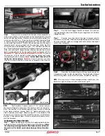
Before Towing, perform a tow bar safety check, look 

for any loose fasteners, condition of safety cables, 

excessive movement in connecting leg shaft when 

the shaft is extended and locked. If any excessive 

movement or loose fasteners are found, the tow 

bar will need to be serviced before towing. 

If tow bar needs servicing, please bring it to an au-

thorized dealer or send it to Demco.  
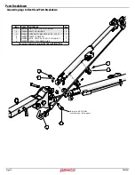
Parts Breakdown

Connecting Leg Parts Breakdown

ITEM #

PART #

DESCRIPTION

Qty

1

00182

HAIR PIN, .120 WIRE X 2.375

1

2

02178

NUT, .50NC LOCK, NY. INSERT

2

3

02397

LYNCH PIN

2

4

03805

WIRE SUPPORT ROD

1

5

03809

CLEVIS SPACER WASHER

4

6

03878

ATTACHING PIN

2

7

07223

ROLL PIN, .156 X .75

1

8

13176

TRIGGER HANDLE

2

9

13179

COMPRESSION SPRING

2

10

13227

PLASTIC BUSHING, .50 ID X .75 LG

2

11

13249

CLEVIS GROOVED PIN, .313 X 1.25, SS

4

12

13250

RETAINING RING F/ .313 SHAFT

4

13

13431

STORAGE PIN

2

14

13432

RETAINING E-CLIP, SS F/ .25 SHAFT

2

15

13527

CONNECTING CLEVIS F/INDEP.ARM TB

2

16

13561

SCREW, BUTTON SOCKET HD, .313NC X .5 SS

16

17

13859

LATCH SEAR

2

18

15352

BOLT .50NC X 2.75 W/1.75 SHANK

2

19

15712

CONNECTING LEG SHAFT

2

20

16702

CONNECTING LEG TUBE, LEFT

1

21

16703

CONNECTING LEG TUBE, RIGHT

1

22

16704

FRONT ADAPTOR

2

Please order replacement parts by PART NO. and DESCRIPTION.

Содержание Excalibar 3

Страница 1: ...TB20061 Rev 2 09 19 SELF ALIGNING TOW BAR Excalibar 3...

Страница 2: ...y Operator Manuals Registration 2 Signal Words 3 Equipment Safety Guidelines 3 Remember 3 Lighting and Marking 3 SAFETY Sign Locations 4 Safety Sign Care 4 Before operation 4 During Operation 5 Highwa...

Страница 3: ...dents occur which could have been avoided by a few seconds of thought and a more careful approach to handling equipment You the operator can avoid many accidents by observing and following precautions...

Страница 4: ...towing unit or towed vehicle Do not use tow bar until you are sure that area is clear especially around children and animals Don t hurry learning process or take tow bar for granted Ease into it and...

Страница 5: ...nless securely positioned and blocked Keep all bystanders and pets clear of work area Operate towing unit from operators seat only As a precaution recheck hardware on tow bar every 200 miles and corre...

Страница 6: ...replacing bolts refer to owners manual Refer to bolt torque chart for head identification marking Where replacement parts are necessary for periodic maintenance and servicing genuine factory replacem...

Страница 7: ...assembly of equipment Torque figures indicated are valid for non greased or non oiled threads and heads unless otherwise specified Therefore do not grease or oil bolts or capscrews unless otherwise sp...

Страница 8: ...transmission pump or drive shaft disconnect Be sure the SAFETY CABLES w retainers are hooked to both the towing and towed vehicles using the crisscross method Do not load the towed vehicle with anythi...

Страница 9: ...eeping matching side together for reassembly 1 Reinstall connecting leg shaft and push shaft all the way in to reinstall latch assembly Install latch as an as sembly put pin on bottom latch sear hole...

Страница 10: ...cked If any excessive movement or loose fasteners the tow bar will need to be serviced before towing The vehicles do not have to be in straight alignment to complete the hook up Engage towed vehicle a...

Страница 11: ...r head so the vertical bolt is perpendicular to the baseplate height of towed vehicle Tighten the 1 2 bolts on each side of joint head to 85 ft lbs If manual transmission shift to neutral unlock steer...

Страница 12: ...13297 BOLT 75 NC X 3 75 W 2 50 SHANK 1 9 13570 TOW BAR RECEIVER 1 5 DROP RISE 1 10 13168 CROSSTUBE BUSHING NYLATRON 2 Please order replacement parts by PART NO and DESCRIPTION ITEM PART DESCRIPTION Q...

Страница 13: ...to Demco Parts Breakdown Connecting Leg Parts Breakdown ITEM PART DESCRIPTION Qty 1 00182 HAIR PIN 120 WIRE X 2 375 1 2 02178 NUT 50NC LOCK NY INSERT 2 3 02397 LYNCH PIN 2 4 03805 WIRE SUPPORT ROD 1 5...

Страница 14: ...UT 50NC LOCK NY INSERT 2 2 13212 RAIL CLIP HOLDER 4 3 13213 SCREW SOCKET HD 8 32 X 625 SS 4 4 13273 SAFETY CABLE 54 2 5 13305 BOLT 50NC X 2 38 W 1 75 SHANK SS 2 6 13317 CLEVIS SPACER WASHER 4 Please o...

Страница 15: ...07 Straight Safety Cable w Hooks 64 2 Please order replacement parts by PART NO and DESCRIPTION ITEM PART DESCRIPTION Qty 9523064 12 Safety Cable Extension Kit 9523065 18 Safety Cable Extension Kit 1...

Страница 16: ...10 Towed Vehicle Tail Light Wiring Diode Kit Only 9523011 9523006 Towed Vehicle Tail Light Wiring Diode Kit 9523054 7 to 6 WayAuxiliary Coiled Lighting Cable w recpt Please order replacement parts by...

Страница 17: ...cement parts by PART NO and DESCRIPTION PARTS LIST 1 ITEM PART DESCRIPTION 9523068 3 Piece Locking Pin Set 1 14054 Tow Bar to Base Plate Single Locking Pin Assembly 2 14047 Tow Bar to Motor Home recei...

Страница 18: ...2 Start engine and have someone depress brake pedal Brake lights of the light bar and towing vehicle should come on and off simultaneously with each applica tion 3 Turn left turn signal on Left turn...

Страница 19: ...TB20061 Page 19...

Страница 20: ......

Отзывы: