26
6.1.3
Basic protocol commands
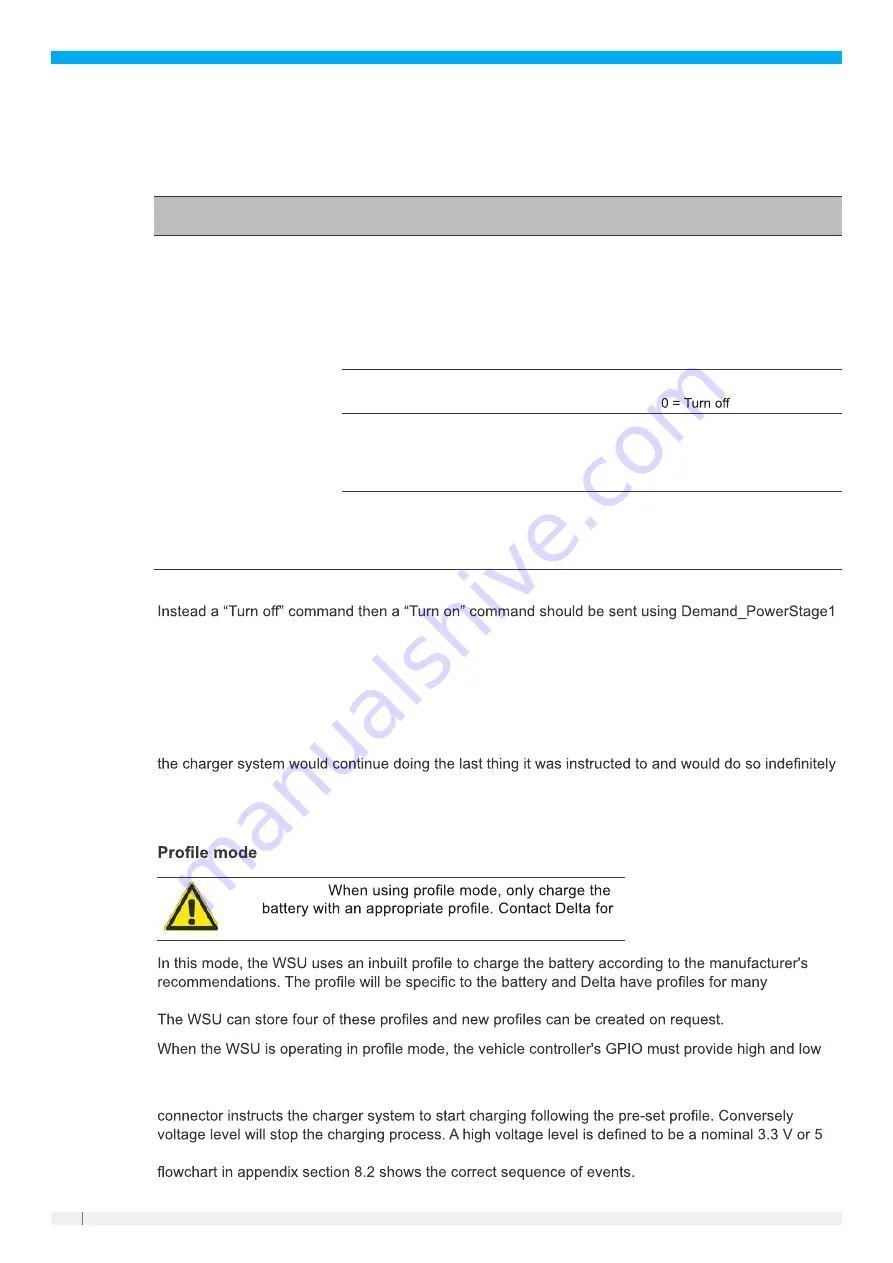
The following table details the essential commands used to control the WSU. The full protocol includes
many more messages, is capable of controlling multiple WSUs on the same bus, and gives detailed
fault and status information.
Message
Name
Message
ID
Signal name Start
bit
Length Factor
Unit Description
ControlModule
0x190
Demand_V
0
20
0.001
V
The target voltage the WCS
is to achieve by providing
current to the battery. When
the battery terminal voltage
reaches this value, the
charging current will reduce
(eventually to 0), to maintain
the voltage.
Demand_
PowerStage1
20
1
1
1 = Turn on
Demand_
ClearFaults
21
1
1
1 = Clear Faults
If the fault condition no
longer exists, charging will
resume
Demand_I
32
18
0.001
A
The maximum current used
to reach or maintain the
target voltage.
Note: ClearFaults will not clear over voltage protection (OVP) and over current protection (OCP).
6.1.4
CAN bus watchdog
If the WSU is under CAN bus control it must receive frequent messages on ID 0x190, otherwise it will
disable its output and indicate “Fault_WD_Comms”. This is an important safety feature as when the
WSU is being controlled by CAN bus, it is the responsibility of the system to ensure safe operation of
the WSU. Without this feature, if the system lost control of the WSU perhaps due to a broken cable,
resulting in a potentially hazardous situation.
It is recommended that the 0x190 message be sent to the WSU every 100 ms.
6.2
►
Caution:
further advice.
manufacturers covering a range of battery constructions, e.g., lithium and lead acid (AGM, gel, TPPL).
logic levels to start and stop the charging process.
A high voltage level presented between pin 1 (“EXT_Enable”) and pin 3 (“EXT_Signal_GND”) of the
, a low
(range 2.7 V to 5.5 V), and a low voltage level should be less than 0.3 V or NC (not connected). The
V


