34
Appendix
9.1
9
Evaluating the charger system without a battery
The best way to see an accurate representation of the charger system performance is to charge a real
battery. However it is possible to evaluate the charger system using an electronic load set to Constant
Voltage mode.
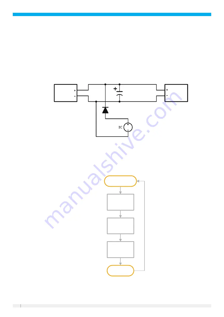
System block diagram in this condition is shown as below. In the test system, to simulate the battery, an
100 mF capacitor need to be connected in parallel at DC output bus, and a pre-charging circuit (including
DC source, diode) is necessary to charge the capacitor to a reasonable voltage value (e.g. 24 V for 24 V
variant, 48 V for 48 V variant) before turning on the wireless charger system.
Electronic
load
100 mF (typ.)
100 V
1 A, 100 V
silicone diode
24 V or 48 V
<1 A current limit
Charger
secondary
box
The charger system performance is not guaranteed when operating with an electronic load.
9.2
Flow chart
Vehicle running,
battery not charging
Vehicle approaching
primary pad
Vehicle docked at
primary pad
Charging
ENABLE on
Charger monitors
battery and follows
inbuilt profile
Vehicle controller
determines charge
should end.
ENABLE off
Vehicle controller
determines charge
should end. Disables
charger
Vehicle controller
sets voltage and
current and sends
to charger every
100 ms
Vehicle controller
sets voltage and
current. Enables
charger
SLEEP mode off
Charge end
SLEEP mode on
(optional)
SLEEP mode on
(optional)
ENABLEoff
SLEEP mode o
ff
ENABLE o
ff
CAN bus mode
Profile mode


