Ethernet Communication Module DVPEN01-SL
DVP-PLC Application Manual
50
M1013
K100
K1
K100
K100
K1
M2
M1
M1
SET
M1
TOP
TOP
TOP
K100
TOP
K1
K100
K1
TOP
K100
TOP
K1
K1
K0
H4
HC0A8
K1
H0
K100
K100
K1
TOP
TOP
K100
TOP
K1
K1
K1
H0
H5
H5
K100
TOP
K1
K100
K100
K1
TOP
TOP
K100
TOP
K1
K1
H0
H0
K6
HFF
K118
K117
K111
K120
K121
K122
K123
K124
K125
K119
K116
K115
K124
= D0 K0
= D0 K1
SET
M2
M1
RST
MOV
K0
D0
= D0 K2
INC
D0
END
K100
K1
M2
D14
RST
M2
RST
M2
= D14 K2
= D14 K3
FROM
K116
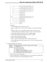
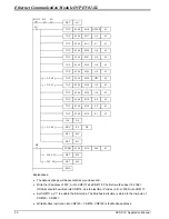
Explanations:
•
The data exchange will be executed every one second.
•
Write the IP address of PLC_A into CR#117 and CR#118. The first two IP codes (192.168 =
H’C0A8) should be written into CR#118, and the last two IP codes (0.4 = H’0004) into CR#117.
•
Set CR#111 as “1” to enable the 8-bit mode. The Modbus instrcution is stored in the low byte of
CR#120 ~ CR#247.
•
Write Modbus instrcution into CR#120 ~ CR#125. CR#120 is the Modbus address.
Содержание Ethernet Communication Module DVPEN01-SL
Страница 1: ...DVPEN01 SL Ethernet Communication Module Application Manual ...
Страница 2: ......
Страница 54: ...Ethernet Communication Module DVPEN01 SL DVP PLC Application Manual 52 MEMO ...


