86
Processor Module
11
Turn the top-cover assembly over.
12
Remove the processor fan and heat-sink assembly (see "Removing the
Processor Fan and Heat-Sink Assembly" on page 79).
CAUTION:
To prevent intermittent contact between the ZIF-socket cam screw
and the processor when removing or replacing the processor, press to apply slight
pressure to the centre of the processor while turning the cam screw.
CAUTION:
To avoid damage to the processor, hold the screwdriver so that it is
perpendicular to the processor when turning the cam screw.
13
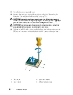
To loosen the ZIF socket, use a small, flat-blade screwdriver and rotate the
ZIF-socket cam screw counterclockwise until it comes to the cam stop.
1
ZIF socket
2
processor module
3
pin-1 corner
4
ZIF-socket cam screw
1
2
4
3
Содержание XPS L401X
Страница 1: ...Dell XPS L401X Service Manual Regulatory model P12G series Regulatory type P12G001 ...
Страница 8: ...8 Contents ...
Страница 12: ...12 Before You Begin ...
Страница 20: ...20 Memory Module s ...
Страница 26: ...26 Wireless Mini Card s ...
Страница 30: ...30 Hard Drive ...
Страница 40: ...40 Palm Rest Assembly ...
Страница 48: ...48 Power Button Board ...
Страница 52: ...52 Coin Cell Battery ...
Страница 64: ...64 Display ...
Страница 68: ...68 Camera Module ...
Страница 74: ...74 Top Cover ...
Страница 78: ...78 Speakers ...
Страница 83: ...Processor Fan and Heat Sink Assembly 83 ...
Страница 84: ...84 Processor Fan and Heat Sink Assembly ...
Страница 92: ...92 Daughter Board ...
Страница 96: ...96 Internal Card With Bluetooth Wireless Technology ...
Страница 100: ...100 AC Adapter Connector ...
Страница 106: ...106 System Board ...
Страница 108: ...108 Flashing the BIOS 8 Double click the file icon on the desktop and follow the instructions on the screen ...


