background image

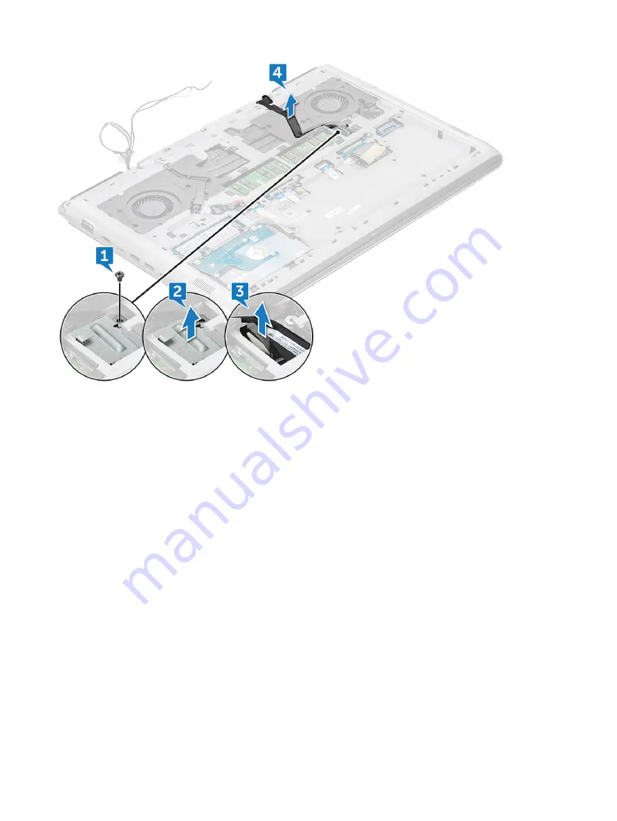
d Unroute the eDP cable from the routing channel [4].

Disconnect the following cables:

a Disconnect the Power, LED and Keyboard backlight cable from the connector on the system board [1].
b Disconnect the touchpad cable from the connector on the system board[2].
c Peel the adhesive tape and disconnect the keyboard cable from the connector on the system board [3, 4].

Sådan fjernes og installeres komponenter

23

Содержание Vostro 15-7580

Страница 1: ...Dell Vostro 15 7580 Owners Manual Forordningsmodel P71F Forordningstype P71F002 ...

Страница 2: ... eller tab af data og oplyser dig om hvordan du kan undgå dette problem ADVARSEL ADVARSEL angiver risiko for tingskade personskade eller død 2018 Dell Inc eller dets datterselskaber Alle rettigheder forbeholdes Dell EMC og andre varemærker er varemærker tilhørende Dell Inc eller deres associerede selskaber Andre varemærker kan være varemærker for deres respektive ejere 2018 02 rev A00 ...

Страница 3: ...attery 13 Møntcellebatteri 14 Removing the coin cell battery 14 Installing the coin cell battery 14 Hukommelsesmoduler 15 Removing the memory module 15 Installing the memory module 15 Harddisk 16 Removing the hard drive 16 Installing the hard drive 17 Solid state drev valgfrit tilbehør 17 Removing the M 2 Solid State Drive SSD 17 Installing the M 2 Solid State Drive SSD 18 WLAN kort 18 Removing th...

Страница 4: ...tur 44 Removing the keyboard 44 Installing the keyboard 46 Skærmmodul 47 Removing the display assembly 47 Installing the display assembly 48 Håndfladestøtte 49 Removing the palm rest assembly 49 Skærmfacet 50 Removing the display bezel 50 Installing the display bezel 52 Camera Kamera 52 Removing the camera 52 Installing the camera 53 Skærmhængsler 54 Removing the display hinge 54 Installing the di...

Страница 5: ... 66 Features 66 Power ConsumptionKey Specifications 66 NVIDIA GeForce GTX 1060 Graphics 67 Features 67 Power ConsumptionKey Specifications 67 4 Systemspecifikationer 69 Processor 69 Memory 69 Video 70 Audio 70 Connectivity options 71 Ports and Connectors 71 Display specifications 71 Keyboard 72 Touchpad 72 Storage 73 Battery specifications 73 Adapter options 74 Webcam specifications 74 System dime...

Страница 6: ...a F12 engangsstartmenuen 91 System and Setup Password System og installationsadgangskode 95 Sådan tildeles systemadgangskode og installationsadgangskode 95 Sletning eller ændring af en eksisterende opsætning af adgangskode 96 6 Software 97 Operating system configurations 97 Chipset drivers 97 USB drivers 98 Network drivers 99 Audio drivers 99 Storage controller drivers 99 Bluetooth drivers 99 Secu...

Страница 7: ...forsynet også når de er slukkede Den interne strøm gør det muligt at tænde for systemet vække på LAN og sætte det på dvaletilstand via fjernbetjening samt andre avancerede strømstyringsfunktioner Hvis du frakobler strømmen og derefter trykker på og holder tænd sluk knappen inde i 15 sekunder aflades systemkortet for reststrøm bærbare pc er Forbindelse Forbindelse er en måde at tilslutte to eller f...

Страница 8: ...æt og forbindelsestråden skal være bindeled imellem måtten og et hvilket som helst blankt metal på det system der arbejdes på Når det hele er korrekt opsat kan du tage servicedele ud af ESD posen og placere dem direkte på måtten ESD følsomme genstande er sikre i din hånd på ESD måtten i systemet eller i en pose Håndledsrem og forbindelsestråd Håndledsremmen og forbindelsestråden kan forbindes dire...

Страница 9: ...er tungt udstyr FORSIGTIG Løft ikke mere end 50 pund Få altid hjælp eller brug en mekanisk løfteanordning 1 Få solidt og fast fodfæste Hold dine fødder let spredte for en stabil base og peg tæerne udad 2 Spænd i mavemusklerne Bugmuskulaturen støtter din ryg når du løfter ved at kompensere for belastningen 3 Løft med dine ben ikke ryggen 4 Hold belastningen tæt ind til kroppen Jo tættere den er på ...

Страница 10: ...ecifikke Dell computer Brug ikke batterier som er beregnet til andre Dell computere 1 Tilslut alle eksterne enheder så som en portreplikator eller mediebase og genmonter alle kort fx ExpressCard 2 Tilslut telefon eller netværkskabler til computeren FORSIGTIG For at tilslutte et netværkskabel skal du først sætte det i netværksenheden og derefter sætte det i computeren 3 Tilslut computeren og alle t...

Страница 11: ...our computer 2 To remove the base cover a Loosen the single M2 5x2 3 5 captive screw that secures the base cover to the system 1 b Pry the base cover from the edge 2 BEMÆRK You may need a plastic scribe to pry the base cover from the edge 3 Lift the base cover away from the system 2 Sådan fjernes og installeres komponenter 11 ...

Страница 12: ...to the system 4 Follow the procedure in After working inside your computer Batteri Removing the battery 1 Follow the procedure in Before working inside your computer 2 Remove the base cover 3 To remove the battery a Disconnect the battery cable from the connector on the system board 1 b Remove the three M2x3 screws that secure the battery to the system 2 12 Sådan fjernes og installeres komponenter...

Страница 13: ...e battery away from the system Installing the battery 1 Insert the battery into the slot on the system 2 Connect the battery cable to the connector on the system board Sådan fjernes og installeres komponenter 13 ...

Страница 14: ... coin cell battery a Disconnect the coin cell battery cable from the connector on the system board 1 b Pry the coin cell battery to release from the adhesive and lift it away from the system board 2 Installing the coin cell battery 1 Place the coin cell battery into the slot on the system board 2 Connect the coin cell battery cable to the connector on the system board 3 Install the a battery b bas...

Страница 15: ...retention clips securing the memory module until the memory pops up 1 b Lift the memory module away from the system 2 Installing the memory module 1 Insert the memory module into the memory module socket until the clips secure the memory module 2 Install the a battery b base cover 3 Follow the procedure in After working inside your computer Sådan fjernes og installeres komponenter 15 ...

Страница 16: ...isconnect the cable a Lift the latch and disconnect the hard drive cable from the system 1 b Pry the hard drive cable to release from the adhesive 2 4 To remove the hard drive a Remove the four M2 5x3 screws that secure the hard drive to the system 1 b Lift the hard drive away from the system 2 16 Sådan fjernes og installeres komponenter ...

Страница 17: ...stem board 5 Install the a battery b base cover 6 Follow the procedure in After working inside your computer Solid state drev valgfrit tilbehør Removing the M 2 Solid State Drive SSD 1 Follow the procedure in Before working inside your computer 2 Remove the a base cover b battery 3 To remove the SSD a Remove the single M2x3 screw that secures the SSD to the system 1 b Slide and lift the SSD from t...

Страница 18: ...cedure in After working inside your computer WLAN kort Removing the WLAN card 1 Follow the procedure in Before working inside your computer 2 Remove the a base cover b battery 3 To remove the WLAN card a Remove the single M2x3 screw that secures the wireless card holder to the system 1 b Remove the wireless card holder that secures the WLAN antenna cables 2 18 Sådan fjernes og installeres komponen...

Страница 19: ...e the wireless card holder to its place and replace the M2x3 screw to secure the holder to the system 4 Install the a battery b base cover 5 Follow the procedure in After working inside your computer Rear cover Removing the rear cover 1 Follow the procedure in Before working inside your computer 2 Remove the a base cover b battery 3 To remove the screws a Remove the four M2x2 screws that secure th...

Страница 20: ... two recess points near the center of the rear cover 2 BEMÆRK You may need a plastic scribe to pry the rear cover from the edge 4 Pry the edges from the left and right side until the retention tabs are released 20 Sådan fjernes og installeres komponenter ...

Страница 21: ...over from the system Installing the rear cover 1 Press the edges of the rear cover until it clicks into place 2 Replace the M2x2 screws that secure the rear cover to the system Sådan fjernes og installeres komponenter 21 ...

Страница 22: ...rd d rear cover 3 To disconnect the cables a Disconnect the camera cable and unroute from the routing channel 1 2 b Unroute the WLAN antenna cables from the routing channel 3 4 4 Disconnect the eDP cable a Remove the single M2x3 screw that secures the eDP metal bracket to the system 1 b Lift the eDP metal tab from the system 2 c Disconnect the eDP cable from the connector on the system board 3 22 ...

Страница 23: ...he Power LED and Keyboard backlight cable from the connector on the system board 1 b Disconnect the touchpad cable from the connector on the system board 2 c Peel the adhesive tape and disconnect the keyboard cable from the connector on the system board 3 4 Sådan fjernes og installeres komponenter 23 ...

Страница 24: ...6 Remove the nineteen M2 5x6 screws that secure the back cover to the system 24 Sådan fjernes og installeres komponenter ...

Страница 25: ...7 Remove the four M2x3 screws and turn over the system 1 2 8 Open the display assembly at 90 angle Sådan fjernes og installeres komponenter 25 ...

Страница 26: ...9 To remove the back cover a Using a plastic scribe pry the edges of the plamrest 1 2 b Lift the plamrest away from the back cover 3 26 Sådan fjernes og installeres komponenter ...

Страница 27: ...10 The component you are left with is the back cover Sådan fjernes og installeres komponenter 27 ...

Страница 28: ...ctors in the system board and affix the adhesive tape over the keyboard cable 5 Route the eDP cable through the routing channel and connect the cable to the system 6 Place the eDP metal bracket and replace the M2x3 screw to secure the eDP to the system 7 Route the camera and WLAN antenna cables through the routing channel and connect the camera cable to the system board 8 Install the a WLAN card b...

Страница 29: ...ver 3 To remove the speaker a Disconnect the speaker cable from the connector in the system board 1 b Unroute the cable from the routing channel 2 3 4 4 Lift the speakers along with the speaker cable away from the back cover Sådan fjernes og installeres komponenter 29 ...

Страница 30: ...rd 4 Install the a back cover b rear cover c memory module d WLAN card e hard drive f SSD card g battery h base cover 5 Follow the procedure in After working inside your computer Systemkort Removing the system board 1 Follow the procedure in Before working inside your computer 2 Remove the a base cover b battery c SSD card d WLAN card e HDD f memory module 30 Sådan fjernes og installeres komponent...

Страница 31: ...emove the following metal tabs a Remove the two M2 5x5 screws that secure the DC in metal bracket on the system board 1 b Lift the metal bracket that secures the power port on the system board 2 c Remove the two M2 5x5 screws that secure the Type C USB metal bracket on the system board 3 d Lift the Type C USB metal bracket that secures the Thunderbolt port on the system board 4 e Disconnect the sp...

Страница 32: ...5 Remove the four M2x3 screws that secure the system fan to the system board 32 Sådan fjernes og installeres komponenter ...

Страница 33: ...screws that secure the system fan to the system board 4 Connect the speaker cable to the system board 5 Place the Type C USB metal bracket on the Thunderbolt port and replace the two M2 5x5 screws that secure the metal bracket to the system board 6 Place the DC in metal bracket on the power port and replace the two M2 5x5 screws that secure the metal bracket to the system board 7 Connect the coin ...

Страница 34: ...2 Remove the a base cover b battery c SSD card d WLAN card e HDD f memory module g rear cover h back cover i system board 3 To remove power connector port a Unroute the power connector port from the routing channel 1 b Remove the power connector port from the system 2 34 Sådan fjernes og installeres komponenter ...

Страница 35: ... HDD g SSD card h battery i base cover 4 Follow the procedure in After working inside your computer Kølelegeme Removing the heat sink assembly 1 Follow the procedure in Before working inside your computer 2 Remove the a base cover b battery c SSD card d WLAN card e HDD f memory module g rear cover h back cover 3 Disconnect the left fan cable 1 and right fan cable 2 from the connectors on the syste...

Страница 36: ...ws 6 5 4 3 2 1 that secure the heat sink assembly to the system board 1 BEMÆRK Remove the screws based on the numbering on the heat sink b Lift the heat sink assembly from the system board 2 5 The component you are left with is the heat sink assembly 36 Sådan fjernes og installeres komponenter ...

Страница 37: ...stem board 4 Connect the two fan cables to the connector on the system board 5 Install the a back cover b rear cover c memory module d SSD card e WLAN card f HDD g battery h base cover 6 Follow the procedure in After working inside your computer Berøringsplade Removing the touchpad 1 Follow the procedure in Before working inside your computer 2 Remove the a base cover b battery c SSD card d WLAN c...

Страница 38: ... Remove the four M2x2 screws that secure the touchpad assembly to the palmrest 1 4 Slide the touchpad assembly from the display assembly 2 5 Lift the touchpad assembly from the palmrest 38 Sådan fjernes og installeres komponenter ...

Страница 39: ...r working inside your computer LED kort Removing the LED board 1 Follow the procedure in Before working inside your computer 2 Remove the a base cover b battery c SSD card d WLAN card e HDD f memory module g rear cover h back cover 3 To remove LED board a Lift the latch and disconnect the LED board cable 1 b Remove the single M2x3 screw that secures the LED board cable to the display assembly 2 c ...

Страница 40: ...ED board cable to the display assembly 4 Install the a back cover b rear cover c memory module d WLAN card e HDD f SSD card g battery h base cover 5 Follow the procedure in After working inside your computer Strømknapkort Removing the power button board 1 Follow the procedure in Before working inside your computer 2 Remove the a base cover 40 Sådan fjernes og installeres komponenter ...

Страница 41: ...rd cable from the power button board 1 b Peel the adhesive tape that covers the power button board cable 2 and pry the power button board cable from the palmrest 4 To remove power button board a Remove the two M2x3 screws that secure the power button board to the palmrest 1 b Remove the power button board from the palmrest 2 Sådan fjernes og installeres komponenter 41 ...

Страница 42: ...er button board to the display assembly 3 Connect the power button board cable to the power button board and affix it to the palmrest 4 Install the a back cover b rear cover c memory module d WLAN card e HDD f SSD card g battery h base cover 5 Follow the procedure in After working inside your computer 42 Sådan fjernes og installeres komponenter ...

Страница 43: ... d WLAN card e HDD f memory module g rear cover h back cover i power button board 3 To release the fingerprint reader a Using a plastic scribe lift the fingerprint reader board 1 b Remove the two M2x2 screws that secure the fingerprint reader to the palm rest 2 c Lift the fingerprint reader away from the palm rest 3 Sådan fjernes og installeres komponenter 43 ...

Страница 44: ...ng the keyboard 1 Follow the procedure in Before working inside your computer 2 Remove the a base cover b battery c SSD card d WLAN card e HDD f memory module g rear cover h back cover i display hinge 3 Disconnect the following cables a power board cable b LED board cable c keyboard backlight cable d touchpad cable e keyboard cable 4 Disconnect the power button board cable from the power button bo...

Страница 45: ...6 Remove the thirty M1 6x2 screws that secure the keyboard bracket to the palmrest and lift the keyboard bracket 1 2 7 Remove the keyboard from the palm rest Sådan fjernes og installeres komponenter 45 ...

Страница 46: ... bracket to the palm rest 4 Connect the following cables a power board cable b LED board cable c keyboard backlight cable d touchpad cable e keyboard cable 5 Install the a display hinge b back cover c rear cover d memory module e WLAN card f HDD g SSD card h battery i base cover 6 Follow the procedure in After working inside your computer 46 Sådan fjernes og installeres komponenter ...

Страница 47: ... b battery c SSD card d WLAN card e HDD f memory module g rear cover h back cover 3 To remove hinge bracket a Remove the two M2 5x5 screws that secure the hinge bracket to the display assembly 1 b Lift the hinge bracket from the display assembly 2 4 Slide and lift the display assembly Sådan fjernes og installeres komponenter 47 ...

Страница 48: ...ent you are left with is the display assembly Installing the display assembly 1 Place the display assembly on the system 2 Place the hinge bracket on the display assembly 48 Sådan fjernes og installeres komponenter ...

Страница 49: ...g the palm rest assembly 1 Follow the procedure in Before working inside your computer 2 Remove the a base cover b battery c coin cell battery d SSD card e memory module f hard drive g WLAN card h rear cover i back cover j touchpad k LED board l power button board m fingerprint reader n keyboard o display assembly p display hinge BEMÆRK After the removal of all the components the component that yo...

Страница 50: ... cover j WLAN card k hard drive l memory module m SSD card n coin cell battery o battery p base cover 4 Follow the procedure in After working inside your computer Skærmfacet Removing the display bezel 1 Follow the procedure in Before working inside your computer 2 Remove the a base cover b battery c SSD card d WLAN card e HDD f memory module 50 Sådan fjernes og installeres komponenter ...

Страница 51: ...play assembly 3 Using a plastic scribe pry the inner bottom and inner side edges to release the display bezel from the display assembly 1 2 4 Remove the display bezel from display assembly Sådan fjernes og installeres komponenter 51 ...

Страница 52: ...play assembly 3 Install the a display assembly b back cover c rear cover d memory module e WLAN card f HDD g SSD card h battery i base cover 4 Follow the procedure in After working inside your computer Camera Kamera Removing the camera 1 Follow the procedure in Before working inside your computer 2 Remove the a base cover b battery c SSD card d WLAN card 52 Sådan fjernes og installeres komponenter...

Страница 53: ...a cable from the connector 2 c Lift the camera away from the system 3 Installing the camera 1 Place and affix the camera on the slot in the display assembly 2 Connect the camera cable to the connector on the display assembly 3 Install the a display bezel b display assembly c back cover d rear cover e memory module f WLAN card g HDD Sådan fjernes og installeres komponenter 53 ...

Страница 54: ...ide your computer 2 Remove the a base cover b battery c SSD card d WLAN card e HDD f memory module g rear cover h back cover i display assembly j display bezel 3 To remove the display hinge a Remove the eight M2 5x2 5 screws that secure the display hinge to the display assembly 1 b Lift the display hinge away from the display assembly 2 54 Sådan fjernes og installeres komponenter ...

Страница 55: ...e procedure in After working inside your computer Skærmpanel Removing the display panel Non touch 1 Follow the procedure in Before working inside your computer 2 Remove the a base cover b battery c SSD card d WLAN card e HDD f memory module g rear cover h back cover i display assembly j display bezel k display hinge 3 Remove the four M2x2 5 screws that secure the display panel to the display assem...

Страница 56: ...ve the adhesive tape that covers the display eDP cable connector 1 b Lift the latch and disconnect the display eDP cable from the connector on the display panel 2 c Lift the display panel 3 56 Sådan fjernes og installeres komponenter ...

Страница 57: ...isplay assembly c back cover d rear cover e memory module f WLAN card g HDD h SSD card i battery j base cover 6 Follow the procedure in After working inside your computer eDP kabel Removing the eDP cable 1 Follow the procedure in Before working inside your computer 2 Remove the a base cover b battery c SSD card d WLAN card e HDD f memory module g rear cover h back cover i display assembly j displa...

Страница 58: ...the routing channel 3 Install the a display hinge b display panel c display bezel d display assembly e back cover f rear cover g memory module h WLAN card i HDD j SSD card k battery l base cover 4 Follow the procedure in After working inside your computer 58 Sådan fjernes og installeres komponenter ...

Страница 59: ...ack cover i display assembly j display bezel k display hinge l display panel m camera n eDP cable 3 The display back cover assembly is the remaining component after removing all the components Installing the display back cover assembly 1 The display back cover assembly is the remaining component after removing all the components 2 Install the a eDP cable b camera c display panel Sådan fjernes og i...

Страница 60: ...e display assembly f back cover g rear cover h memory module i WLAN card j HDD k SSD card l battery m base cover 3 Follow the procedure in After working inside your computer 60 Sådan fjernes og installeres komponenter ...

Страница 61: ...OS 1 Restart Power on your computer 2 At the first text on the screen or when the Dell logo appears tap F2 until the message Entering Setup appears 3 Under General Battery Information you will see AC Adapter listed DDR4 DDR4 hukommelse Double Data Rate fjerde generation er en efterfølger til DDR2 og DDR3 teknologierne som har højere hastigheder og op til 512 GB i kapacitet sammenlignet med maksimu...

Страница 62: ...indhak Øget tykkelse DDR4 moduler er en smule tykkere end DDR3 for at kunne tilpasse sig flere signallag Figur 2 Forskel i tykkelse Buet kant DDR4 moduler har en buet kant til at hjælpe med indsættelsen og lette trykket på PCB en under hukommelsesinstallation Figur 3 Buet kant Hukommelsesfejl Hukommelsesfejl på systemskærmen den nye fejlkode ON FLASH FLASH eller ON FLASH ON Hvis al hukommelse fejl...

Страница 63: ...rførsel og understøtning af nye overførselstyper USB 2 0 bagudkompatibilitet Nye stik og kabler Emnerne herunder dækker nogle af de mest almindeligt stillede spørgsmål til USB 3 0 USB 3 1 Gen 1 Hastighed Aktuelt er der 3 hastighedstilstande defineret i de seneste USB 3 0 USB 3 1 Gen 1 specifikationer Disse er Super Speed Superhastighed Hi Speed Højhastighed og Full Speed Fuld hastighed Den nye Sup...

Страница 64: ...j til produkter der tidligere ikke var USB egnede som eksempelvis RAID lagersystemer Herunder er oplistet nogle tilgængelige SuperSpeed USB 3 0 USB 3 1 Gen 1 produkter USB 3 0 USB 3 1 Gen 1 harddiske til ekstern pc Bærbare USB 3 0 USB 3 1 Gen 1 harddiske Dockingstationer og adaptere til USB 3 0 USB 3 1 Gen 1 drev USB 3 0 USB 3 1 Gen 1 flash drev og læsere USB 3 0 USB 3 1 Gen 1 solid state drev USB...

Страница 65: ...ndes samtidig med at enheden sender data via forbindelsen Dette kan betyde et farvel til alle de mange producentspecifikke opladningskabler til bærbare pc er til fordel for en standard USB forbindelse der kan oplade alting Du vil kunne oplade din bærbare pc vha et af de bærbare batterier du oplader dine smartphones og andre bærbare enheder med i dag Du vil kunne slutte din bærbare pc til en ekster...

Страница 66: ... DirectX 12_1 NVIDIA GeForce GTX 1050Ti Graphics The Nvidia GTX 1050 Tiis a mainstream GPU based on the Pascal architecture and was announced in January 2017 Contrary to the faster models the GTX 1050 Ti uses the GP107 chip Features The GP107 chip is manufactured in a 14 nm FinFET process at Samsung and offers a number of new features including support for DisplayPort 1 4 ready HDMI 2 0b HDR Simul...

Страница 67: ...GTX 1060 the laptop version offers the same amount of shader but slightly lower clock rates Features The GP106 chip is produced in 16nm FinFET at TSMC and offers a range of new features like DisplayPort 1 4 ready HDMI 2 0b HDR Simultaneous Multi Projection SMP and improved H 265 video de and encoding PlayReady 3 0 Power Consumption NVIDIA GeForce GTX 1060 Graphics can be found in several notebook ...

Страница 68: ...Specification NVIDIA GeForce GTX 1060 Shared Memory No Technology 16 nm Features Multi Projection G SYNC Vulkan Multi Monitor DirectX DirectX 12_1 68 Teknologi og komponenter ...

Страница 69: ...ics 630 Intel Core i7 8750H up to 4 0 Ghz Intel R UHD Graphics 630 Memory Your computer supports a maximum of 32 GB of memory of memory when you use two 16 GB DIMMs Moreover certain components within the computer require address space in the 4 GB range Any address space reserved for these components cannot be used by computer memory therefore the amount of memory available to a 32 bit operating sy...

Страница 70: ...aphics with 6GB GDDR5 vRAM External display support On system eDP internal display HDMI 2 0 Type C port with Thunderbolt 3 VGA DisplayPort 1 2 Audio Tabel 8 Audio Features Specification Type Integrated High Quality Stereo Speakers Stereo conversion 24 bit analog to digital and digital to analog Internal Interface High definition audio codec External Interface Microphone in and stereo headphones sp...

Страница 71: ...tal to analog Integrated High Quality Stereo Speakers Universal Headphone Jack Internal Interface high definition audio codec Integrated dual array microphone External Interface microphone in and stereo headphones speakers universal connector Speakers Power Peak Power 2X2Wrms 2X2 5Wpeak Internal speaker amplifier 2 watt per channel Internal microphone digital microphone dual microphone with camera...

Страница 72: ...ecifications Number of keys 101 US 102 UK 105 Japan Layout US UK Japan Size Full sized Key travel 1 4 mm Touchpad Tabel 13 Touchpad X Y position resolution 1637 3061 Size Sensor active area X axis 105 mm Y axis 80 mm X Y position resolution X 41 27 4 13 counts mm Y 38 75 3 88 counts mm 1048 984 cpi Multi Touch Configurable single finger and multi finger gestures Tabel 14 Supported gestures Support...

Страница 73: ...TA SSD 256 GB M 2 2280 SATA SSD 256 GB M 2 2230 PCIe NVMe SSD 512 GB M 2 2230 PCIe NVMe SSD Intel Optane memory 16 GB 32 GB Dual drive storage scenario M 2 SSD 2 5 inch HDD Battery specifications This topics lists out the detailed battery specifications Tabel 16 Battery specification 56 Whr 4 Cell Prismatic with ExpressCharge Type Li polymer Dimension Length 233 06 mm 9 170 inch Width 90 73 mm 3 5...

Страница 74: ...pter Specifications Input voltage 100 to 240 VAC 100 to 240 VAC Input current max 2 5 A 2 5 A Input Frequency 50 Hz to 60 Hz 50 Hz to 60 Hz Output current 6 7 A continuous 9 23 A continuous Rated output voltage 19 5 VDC 19 5 VDC Weight lbs 1 15 1 25 Weight kg 0 52 0 57 Dimensions HxWxD inches 1 0x3 0x6 1 1 2 x 3 0 x 6 1 Dimensions HxWxD mm 25 4x 76 2 x 154 94 30 48 x 76 2 x 154 94 Temperature rang...

Страница 75: ... 94 inch Back 24 95 mm 0 98 inch Width 389 0 mm 15 31 inch Depth 270 0 mm 10 62 inches BEMÆRK System weight and shipping weight is based on a typical configuration and may vary based on the actual configuration Environmental Feature Specification Temperature range Operating 10 C to 35 C 50 F to 95 F Storage 40 C to 65 C 40 F to 149 F Relative humidity maximum Storage 20 to 80 non condensing Maximu...

Страница 76: ...Maximum Altitude Operating 15 2 to 3048 m 50 to 10 000 ft Storage 15 2 to 10 668 m 50 to 35 000 ft 76 Systemspecifikationer ...

Страница 77: ...Diagnostics Diagnosticering og BIOS Setup BIOS konfiguration er også tilgængelige i menuen Enhederne i menuen Start afhænger af systemets startenheder Denne menu er nyttig hvis du forsøger at starte fra en bestemt enhed eller vil køre en diagnosticering af systemet Brug af startmenuen ændrer ikke på den startrækkefølge der er lagret i BIOS Indstillingerne er UEFI Boot UEFI start Windows Boot Manag...

Страница 78: ...viser computerens primære hardwarefunktioner Indstillingerne er System Information Memory Configuration Hukommelseskonfiguration Processor Information Processoroplysninger Device Information Enhedsoplysninger Battery Information Viser batteriets status og vekselstrømsadaptertypen der er koblet til computeren Boot Sequence Lader dig ændre rækkefølgen i hvilken computeren forsøger at finde et operat...

Страница 79: ...network controller Click one of the following options Disabled Enabled Enabled w PXE Default SATA Operation Allows you to configure the operating mode of the integrated SATA hard drive controller Click one of the following options Disabled AHCI RAID On Default BEMÆRK SATA is configured to support RAID mode Drives Allows you to enable or disable various drives on board The options are SATA 0 SATA 1...

Страница 80: ...Only USB PowerShare This field configures the USB PowerShare feature behavior This option allows you to charge external devices using the stored system battery power through the USB PowerShare port disabled by default Enable USB PowerShare Audio Allows you to enable or disable the integrated audio controller By default the Enable Audio option is selected The options are Enable Microphone Enable In...

Страница 81: ...eous devices Allows you to enable or disable the following devices Enable Camera Enable Hard Drive Free Fall Protection This options are set by default Indstillinger for videoskærm Tabel 22 Video Egenskab Beskrivelse LCD Brightness Lader dig indstille skærmens lysstyrke afhængigt af strømkilden På batteri 50 er standard og på vekselstrøm 100 standard Security Tabel 23 Security Option Description A...

Страница 82: ... once you set the password BEMÆRK For the first time login Enter the old password field is marked to Not set Hence password has to be set for the first time you login and then you can change or delete the password Strong Password Allows you to enforce the option to always set strong password Enable Strong Password This option is not set by default Password Configuration You can define the length o...

Страница 83: ...password is set Enable Admin Setup Lockout This option is not set by default Master Password Lockout Allows you to disable master password support Enable Master Password Lockout This option is not set by default BEMÆRK Hard Disk password should be cleared before the settings can be changed Secure boot Tabel 24 Secure Boot Option Description Secure Boot Enable Allows you to enable or disable the Se...

Страница 84: ... af følgende muligheder Disabled Deaktiveret Enabled Aktiveret Softwarestyret Standardværdi Enclave Memory Size Denne indstilling angiver SGX Enclave Reserve Memory Size Reservehukommelsesstørrelse for SGX Enclave Klik på en af følgende muligheder 32 MB 64 MB 128 MB Standardværdi Performance Tabel 26 Performance Option Description Multi Core Support This field specifies whether the process has one...

Страница 85: ...r Management Option Description AC Behavior Allows you to enable or disable the computer from turning on automatically when an AC adapter is connected Wake on AC This option is not set by default Enable Intel Speed Shift Technology Allows you to enable or disable the Intel Speed Shift Technology Enabled Default Auto On Time Allows you to set the time at which the computer must turn on automaticall...

Страница 86: ...s over a shorter period of time using Dell s fast charging technology Primarily AC use Custom If Custom Charge is selected you can also configure Custom Charge Start and Custom Charge Stop BEMÆRK All charging mode may not be available for all the batteries To enable this option disable the Advanced Battery Charge Configuration option Post behavior Tabel 28 POST Behavior Option Description Adapter ...

Страница 87: ...when either warnings or errors are detected during the POST process Click one of the following options Prompt on Warnings and Errors Default Continue on Warnings Continue on Warnings and Errors Virtualiseringsunderstøttelse Tabel 29 Virtualization Support Virtualiseringsunderstøttelse Egenskab Beskrivelse Virtualization Dette felt angiver om en VMM Virtual Machine Monitor kan anvende de yderligere...

Страница 88: ...erede er angivet en aktivkode Denne indstilling er som standard ikke angivet BIOS Downgrade Gør det muligt for dig at flashe tidligere revisioner af systemfirmwaren Allow BIOS Downgrade Tillad BIOS nedgradering Denne indstilling er som standard valgt Data Wipe Gør det muligt for dig at slette data fra alle interne lagerenheder på en sikker måde Wipe on Next Boot Denne indstilling er som standard i...

Страница 89: ...atiske start flow for SupportAssist systemopløsningskonsollen og for Dells OS gendannelsesværktøj Klik på en af følgende muligheder SLUKKET 1 2 Standardværdi 3 SupportAssist OS Recovery Lader dig gendanne SupportAssist OS gendannelse deaktiveret som standard Sådan opdateres BIOS en i Windows Det anbefales at opdatere din BIOS Systemopsætning ved udskiftning af systemkortet eller hvis der findes en...

Страница 90: ...lket systemet vil bede dig om efter hver genstart Hvis du ikke kender gendannelseskoden kan dette resultere i tab af data eller unødvendig geninstallation af operativsystem Du kan finde flere oplysninger om dette emne i Knowledge artiklen http www dell com support article us en 19 SLN153694 updating bios on systems with bitlocker enabled Sådan opdaterer du din system BIOS ved hjælp af USB flashdre...

Страница 91: ... Hvis indstillingen er indstillet understøtter BIOS en denne BIOS opdateringsform BEMÆRK Kun systemer med indstillingen BIOS flashopdatering i F12 engangsstartmenuen kan anvende denne funktion Sådan opdateres der fra engangsstartmenuen For at opdatere din BIOS fra F12 engangsstartmenuen har du brug for USB nøgle formateret til FAT32 filsystemet nøgler behøver ikke at være opstartsbare Eksekverbar ...

Страница 92: ...3 Flash menuen for BIOS en åbnes Klik derefter på Gennemse 4 E5450A14 exe filen vises som eksempel på det følgende skærmbillede Det faktiske filnavn kan variere 92 Systeminstallationsmenu ...

Страница 93: ...5 Når filen er valgt vises den i boksen med valgte filer og du kan klikke på OK for at fortsætte 6 Klik på knappen Begin Flash Update Begynd flashopdatering Systeminstallationsmenu 93 ...

Страница 94: ...t påbegyndes BIOS flash systemet genstarter og så starter BIOS flash og en statuslinje viser flash processen Afhængig af ændringerne inkluderet i opdateringen kan statuslinjen gå fra 0 til 100 adskillige gange og flash processen kan tage op til 10 minutter Generelt tager denne proces to til tre minutter 94 Systeminstallationsmenu ...

Страница 95: ...mputeren FORSIGTIG Adgangskodefunktionerne giver et grundlæggende sikkerhedsniveau for computerens data FORSIGTIG Enhver kan få adgang til de data der er gemt på computeren hvis den ikke er låst og uden opsyn BEMÆRK Funktionen System and Setup Password System og installationsadgangskode er deaktiveret Sådan tildeles systemadgangskode og installationsadgangskode Du kan kun tilknytte en ny systemadg...

Страница 96: ...tus Adgangskodestatus er Locked Låst Tryk på F2 for at gå til systeminstallationsmenuen straks efter en start eller genstart 1 Vælg i skærmen System BIOS eller System Setup Systeminstallationen System Security Systemsikkerhed og tryk Enter Skærmen System Security Systemsikkerheds vises 2 Bekræft i skærmen System Security Systemsikkerhed at Password Status Adgangskodestatus er Unlocked Ulåst 3 Vælg...

Страница 97: ... drivers Bluetooth drivers Security drivers Operating system configurations This topic lists the operating system supported by Vostro 7580 Tabel 35 Operating systems Windows 10 Microsoft Windows 10 Home 64 bit Microsoft Windows10 Professional 64 bit Others Ubuntu 16 04 LTS 64 bit Chipset drivers Verify if the Intel chipset and Intel Management Engine Interface drivers are already installed in the ...

Страница 98: ...USB drivers Verify if the USB drivers are already installed in the computer 98 Software ...

Страница 99: ...installed in the computer Storage controller drivers Verify if the storage controller drivers are already installed in the computer Bluetooth drivers This platform supports a variety of Bluetooth drivers The following is an example Security drivers Verify if the security drivers are already installed in the system Software 99 ...

Страница 100: ...100 Software ...

Страница 101: ...terminalen når der udføres diagnosticeringstests Kørsel af ePSA diagnosticeringen 1 Start diagnosticeringsopstart ved brug af en af demetoder der er foreslået ovenfor 2 I opstartsmenuen skal du ved hjælp af op ned piletasterne gå til ePSA eller diagnosticering og trykke på return tasten Enter for at starte 1 Fn PWR will flash diagnostics boot selected on screen and launch ePSA diagnostics directly...

Страница 102: ...hukommelse ugyldig hukommelse installeret 2 6 systemkort chipsæt systemkort chipsæt fejl 2 7 display skærmfejl 3 1 RTC strømfejl fejl ved knapcellebatteri 3 2 PCI Video PCI videokort chipfejl 3 3 BIOS gendannelse 1 gendannelsesafbildning ikke fundet 3 4 BIOS gendannelse 2 gendannelsesafbildning fundet men ugyldig Batteristatusindikatorer Hvis computeren er tilsluttet en stikkontakt virker batterii...

Страница 103: ...y Notifications of firmware updates and port disablement Examples include Wake on LAN and LAN Cable detect Dell Thunderbolt Dock TB16 and Dell Dock WD15 Wake on dock attached Dock will power on the system automatically Dell Thunderbolt Dock TB16 and Dell Dock WD15 Cable FW updates Ability to receive future enhancements or fixes from Dell Dell Thunderbolt Dock TB16 and Dell Dock WD15 Cable LED Indi...

Страница 104: ...ery charges slowly when connected to the power adapter The hybrid power feature in the Vostro 15 7580 systems enable the battery to output power to the system during heavy loading and in certain gaming conditions to support overall system power demand as long as battery capacity is above 10 Battery charging will resume immediately as soon as the system exits the heavy loading condition 104 Fejlfin...

Страница 105: ...ice Tilgængeligheden varierer for de enkelte lande og produkter og nogle tjenester findes muligvis ikke i dit område Sådan kontakter du Dell omkring salg teknisk support eller kundeservice 1 Gå til Dell com support 2 Vælg supportkategori 3 Bekræft dit land eller område i rullemenuen Choose a Country Region Vælg land område fra listen nederst på siden 4 Vælg det relevante service eller supportlink ...

Отзывы: