background image

Connecting a DC Power Supply to the Power Source

To connect a DC PSU to the site’s DC power source, follow these steps.
Each DC power supply (PSU) comes with a connector cable. One cable is 
provided for each DC PSU.

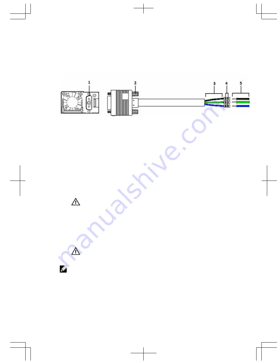
Figure 12. DC Power Supply and Connector Cable

1.

DC PSU power socket.

2.

Cable connector thumb screw.

3.

Cable connector wires (black, green, blue).

4.

Wiring block and screws.

5.

DC power source wires (black, green, blue).

1.

Strip 1/2 inches of insulation from each of the site’s DC power source 
wires (black, green, blue). See item 5 in the figure.

2.

Insert each of the site’s DC power source’s bare wire lengths into the 

wiring block, matching wire colors. See items 3 and 4 in the figure.

WARNING: Do not cross the wires — In the wiring block, blue 
aligns with blue, green aligns with green, and black aligns with 
black.

3.

Use a flat-blade screwdriver to tighten the screws that secure the bare 

wires into the wiring block.

4.

Insert the DC power connector cable end into the power socket of the 

DC PSU and tighten the thumb screws. See items 1 and 2 in the figure.

WARNING: Never try to force the power connector into or out of 
the DC PSU power socket.

NOTE: To remove the power connector from a DC PSU, unscrew the 

thumb screws and pull the power connector from the DC PSU socket.

21

Содержание S6010-ON

Страница 1: ...Dell Networking S6010 ON Getting Started Guide Regulatory Model S6010 ON ...

Страница 2: ......

Страница 3: ...Dell Networking S6010 ON Getting Started Guide Regulatory Model S6010 ON ...

Страница 4: ...problem WARNING A WARNING indicates a potential for property damage personal injury or death Copyright 2016 Dell Inc All rights reserved This product is protected by U S and international copyright and intellectual property laws Dell and the Dell logo are trademarks of Dell Inc in the United States and or other jurisdictions All other marks and names mentioned herein may be trademarks of their res...

Страница 5: ...ttp www dell com support The Dell Networking S6010 ON Installation Guide describes installation and replacement procedures The Dell Networking Configuration Guide for the S6010 ON System describes software configuration The Dell Networking Command Line Reference Guide for the S6010 ON System provides command line interface CLI information The Dell Networking Release Notes for the S6010 ON System p...

Страница 6: ...4 ...

Страница 7: ...nrestricted Temperature around the unit does not exceed 113 F 45 C If the switch is in a closed or multi rack assembly the temperature might be higher than normal room temperature Humidity around the switch does not exceed 95 percent Altitude at the installation site is below 10 000 feet The switch is installed in an environment as free as possible from dust and foreign conductive material such as...

Страница 8: ... cool air intake and to avoid hot air blow out from the I O side ensure that you have the necessary clearance Reliable earthing Maintain reliable earthing of rack mounted equipment Pay particular attention to the supply connections other than the direct connections to the branch circuit for example use of power strips Do not mount the equipment with the PSU side facing in a downward position NOTE ...

Страница 9: ...sis You must supply A wire that complies with your local electrical codes in size and color typically the wire is 14 AWG colored green or green with a yellow stripe An anti oxidant compound Dell Networking recommends NOALOX 4 or equivalent A crimping tool A thread locker compound Dell Networking recommends Threadlocker Blue 242 or equivalent 1 Attach the end of the ground wire to the GND lug a Coa...

Страница 10: ...Figure 1 Ground Wire End and GND Lug Opening 2 Apply the thread locker compound to the two flat head screws then attach the GND lug to the L bracket 8 ...

Страница 11: ... to the S6010 ON chassis a Apply the thread locker compound to the two pan head screws b Attach the GND lug and bracket assembly to the two hole chassis ground connector nuts on the S6010 ON PSU side tightening the screws to ensure torque between 3 5 inch lbs 9 ...

Страница 12: ...tall your switch The Dell ReadyRails system is provided for 1U front rack and two post installations The ReadyRails system includes two separately packaged rail assemblies and two rails that are shipped attached to the sides of the switch Install the ReadyRails system using the 1U tool less method or one of three possible 1U tooled methods two post flush mount two post center mount or four post th...

Страница 13: ...n and seat the front flange pegs in the holes on the front side of the vertical post 3 Repeat this procedure for the second rail 4 To remove each rail pull on the latch release button on each flange ear and unseat each rail Figure 4 1U Tool less Configuration Two Post Flush Mount Configuration To install the Dell ReadyRails system using the two post flush mount configuration follow these steps 1 F...

Страница 14: ... to the front post flange with two user supplied screws See item 2 in the following figure 3 Slide the plunger bracket forward against the vertical post and secure the plunger bracket to the post flange with two user supplied screws See item 3 in the following figure 4 Repeat this procedure for the second rail Figure 5 Two Post Flush Mount Configuration 12 ...

Страница 15: ...rd until it clicks into place and secure the bracket to the front post flange with two user supplied screws See item 1 in the following figure 2 Slide the back bracket towards the post and secure it to the post flange with two user supplied screws See item 2 of the following figure 3 Repeat this procedure for the second rail Figure 6 Two Post Center Mount Configuration 13 ...

Страница 16: ...ear castings from each end of the ReadyRails assemblies Use a Torx driver to remove the two screws from each flange ear and remove each casting See item 1 of the following figure Retain the castings for future rack requirements 2 For each rail attach the front and rear flanges to the post flanges with two user supplied screws at each end See item 2 of the following figure 14 ...

Страница 17: ...the system in the 1U front rack or 1U two post flush and center configurations For the 1U two post flush and center configurations slide the system into the rails in the same manner as the four post configurations The following is an example of a 1U front rack configuration 15 ...

Страница 18: ...ont standoff with the locking tab Figure 8 Attaching the Switch Rails 2 After you have installed both switch rails line them up on the previously mounted Ready Rails and slide the switch in item 1 in the following figure until it is flush with front of rack About 3 inches before you fully insert your system the rail locking feature items 2 and 3 engages to keep the switch from inadvertently slidin...

Страница 19: ...leting the Ground Wire Installation After you have installed the S6010 ON switch in a rack complete the installation of the ground wire You previously installed the GND lug and bracket assembly with ground wire attached to the S6010 ON chassis see Installing the Ground Lug and Bracket Assembly You must supply 17 ...

Страница 20: ... Insert the end of the wire into the lug c Crimp the lug end to secure the connection Figure 10 Ground Wire End and GND Lug Opening 3 Install the second GND lug in compliance with NEC guidelines at the desired location on your rack to be used for grounding the switch a Ensure the rack mating surface is clean b Bring any bare metal to a bright finish c Apply the anti oxidant compound to the mating ...

Страница 21: ... side includes two slots PSU1 and PSU2 Although the switch can run on one PSU Dell Networking highly recommends using two PSUs for full redundancy and additional cooling To avoid overheating when the switch is running with only a single PSU Dell Networking recommends using PSU1 on the left when facing the PSU side and covering the second PSU slot opening PSU2 with a blank plate WARNING Do not comb...

Страница 22: ...h PSU to the external power source only after the chassis is mounted in a rack or cabinet CAUTION The S6010 ON contains two power cords Disconnect both power cords before servicing Connecting a DC Power Supply to the Power Source To connect a DC PSU to the site s DC power source follow these steps Each DC power supply PSU comes with a connector cable One cable is provided for each DC PSU Figure 12...

Страница 23: ...you install a second redundant power supply NOTE To run the system the five fan slots must have operating fan units If you do not install a module in each slot the system shuts down in one minute NOTE The system supports two airflow direction options You can only use a single direction in a chassis Normal is airflow from the I O side to the power supply Reversed is airflow from the power supply to...

Страница 24: ...s of 10GbE small form factor pluggable plus SFP The 32 ports also include eight ports 13 20 that are 40GbE quad small form factor pluggable plus QSFP For a list of supported optics see the S6010 ON Specification Sheet at https www dell com support or contact your Dell Networking representative CAUTION ESD damage can occur if the components are mishandled Always wear an ESD preventive wrist or heel...

Страница 25: ...unit which may be higher than the room temperature is within the limits specified for the system There is sufficient airflow around the unit The input circuits are correctly sized for the loads and that you use sufficient overcurrent protection devices All protective covers are in place CAUTION ESD damage can occur if the components are mishandled Always wear an ESD preventive wrist or heel ground...

Страница 26: ...After Installing the S6010 ON After you have securely installed and powered on the S6010 ON to configure your system see your ONIE compatible operating system documentation 24 ...

Страница 27: ...for the switch to communicate with the local routers and the Internet The minimal configuration provided here does not cover most of the features it simply allows you to perform other configuration tasks using a Telnet connection from your management network IP Settings To set up the switch get the following information from your network administrator Switch IP address Subnet mask IP netmask Defau...

Страница 28: ...0 ON system Therefore use a console connection when connecting to the system for the first time Before starting this procedure be sure that you have a terminal emulation program already installed on your PC 1 Install an RJ 45 copper cable into the console port Use a rollover cable to connect the S6010 ON console port to a terminal server 2 Connect the other end of the cable to the DTE terminal ser...

Страница 29: ...DTE Terminal Server S6010 ON Console Port RJ 45 to RJ 45 Rollover Cable RJ 45 to RJ 45 Rollover Cable RJ 45 to DB 9 Adapter Terminal Server Device Signal RJ 45 Pinout RJ 45 Pinout DB 9 Pin Signal NC 1 8 8 CTS NC 2 7 6 DSR TxD 3 6 2 RxD GND 4 5 5 GND GND 5 4 5 GND RxD 6 3 3 TxD NC 7 2 4 DTR NC 8 1 7 RTS Default Configuration When you install the Dell Networking OS onto your S6010 ON system it is no...

Страница 30: ...e no shutdown 2 Place the interface in Layer 2 switching mode INTERFACE mode switchport To view the interfaces in Layer 2 mode use the show interfaces switchport command in EXEC mode Configuring a Host Name The host name appears in the prompt The default host name is Dell Host names must start with a letter end with a letter or digit and must have characters letters digits and hyphens in the strin...

Страница 31: ...p address ip address mask 3 Enable the interface INTERFACE mode no shutdown Configuring the Management Route Define a path from the S6010 ON to the network from which you are accessing the S6010 ON remotely Management routes are separate from IP routes and are used to manage the S6010 ON through the management port Configure a management route to the network from which you are accessing the system...

Страница 32: ...s using the enable secret password To access EXEC Privilege mode create a password CONFIGURATION mode enable password secret level level encryption type password Creating a Port based VLAN The default VLAN VLAN 1 is part of the system startup configuration and does not require configuration To configure a port based VLAN create the VLAN and then add physical interfaces or port channel LAG interfac...

Страница 33: ...ect the System to the Network After you have completed the hardware installation and software configuration for the system connect to your company network by following your company s cabling requirements 31 ...

Страница 34: ...32 ...

Страница 35: ... 1 71 inches 43 5 mm Width 17 09 inches 434 mm Depth Chassis 18 11 inches 460 mm Chassis weight with factory installed components 21 1 lbs 9 55 kg Rack clearance required I O side 5 inches 12 7 cm PSU side 5 inches 12 7 cm Table 3 Environmental Parameters Parameter Specifications Operating temperature 32 to 113 F 0 to 45 C Operating humidity 5 to 90 percent RH noncondensing Storage temperature 40 ...

Страница 36: ... Typical Power Consumption 417 Watts Table 5 DC Power Requirements Parameter Specifications Minimum maximum input voltage range 40 5V 48V 60V Input power at full load 40 5V 970W 48V 930W 60V 950W without fan 40 5V 980W 48V 940W 60V 960W with fan Input current at full load 40 5V 23 8A 48V 19 0A 60V 15 6A without fan 40 5V 24A 48V 19 2A 60V 16 0A with fan Start up VDC 39 0 1 5V Start off VDC 37 5 1 ...

Страница 37: ...Guía de introducción de Dell Networking S6010 ON Modelo reglamentario S6010 ON ...

Страница 38: ... daños materiales lesiones corporales o incluso la muerte Copyright 2016 Dell Inc Todos los derechos reservados Este producto está protegido por leyes internacionales y de los Estados Unidos sobre los derechos de autor y la protección intelectual Dell y el logotipo de Dell son marcas comerciales de Dell Inc en los Estados Unidos y en otras jurisdicciones El resto de marcas y nombres que se mencion...

Страница 39: ... describen los procedimientos de instalación y sustitución En Dell Networking Configuration Guide for the S6010 ON System Guía de configuración de Dell Networking para el sistema S6010 ON se describe la configuración del software En Dell Networking Command Line Reference Guide for the S6010 ON System Guía de referencia de línea de comandos Dell Networking para el sistema S6010 ON se proporciona in...

Страница 40: ...4 ...

Страница 41: ... se colocan de manera segura lejos de otros dispositivos que puedan dañarlos Si es necesario deje un espacio de una unidad de bastidor RU entre los dispositivos para dejar espacio para los cables El flujo de aire puede circular libremente en torno al conmutador y alrededor de las rejillas de ventilación La temperatura alrededor de la unidad no debe superar los 45 C 113 F Si el conmutador está inst...

Страница 42: ...tura ambiental elevada si la instalación se realiza en un ensamblaje de bastidor cerrado la temperatura de funcionamiento del entorno del bastidor puede ser mayor a la temperatura ambiental de la sala Los intervalos de temperatura ambiental aceptables se muestran en el apartado Especificaciones técnicas bajo Parámetros medioambientales Flujo de aire reducido instale el equipo en el bastidor respet...

Страница 43: ...a antes de empezar Installing the Ground Lug and Bracket Assembly Install the ground GND lug and bracket assembly with a ground wire attached before you install the S6010 ON switch in a rack Dell Networking supplies a kit with the following One two hole UL certified GND lug L bracket Two flat head screws to attach lug to bracket Two pan head screws to attach assembly to chassis You must supply A w...

Страница 44: ...Figure 1 Ground Wire End and GND Lug Opening 2 Apply the thread locker compound to the two flat head screws then attach the GND lug to the L bracket 8 ...

Страница 45: ... to the S6010 ON chassis a Apply the thread locker compound to the two pan head screws b Attach the GND lug and bracket assembly to the two hole chassis ground connector nuts on the S6010 ON PSU side tightening the screws to ensure torque between 3 5 inch lbs 9 ...

Страница 46: ...yRails se proporciona para instalaciones un bastidor frontal de 1U y de dos postes El sistema ReadyRails incluye dos ensamblajes de rieles empaquetados por separado y dos rieles que se envían fijados a los lados del conmutador Instale el sistema ReadyRails utilizando el método sin herramientas para 1U o uno de los tres posibles métodos con herramientas para 1U montaje a ras de dos postes montaje c...

Страница 47: ...3 Repeat this procedure for the second rail 4 To remove each rail pull on the latch release button on each flange ear and unseat each rail Figure 4 1U Tool less Configuration Configuración de montaje a ras de dos postes Para instalar el sistema Dell ReadyRails utilizando la configuración del montaje a ras de dos postes siga estos pasos 1 Para esta configuración debe extraer las piezas fundidas de ...

Страница 48: ...l usuario Consulte el elemento 2 en la ilustración siguiente 3 Deslice el soporte del pistón hacia adelante contra el poste vertical y fije el soporte del pistón a la brida del poste con dos tornillos proporcionados por el usuario Consulte el elemento 3 en la ilustración siguiente 4 Repita este procedimiento con el segundo riel Ilustración 5 Configuración de montaje a ras de dos postes 12 ...

Страница 49: ...gar y fije el soporte a la brida del poste frontal con dos tornillos proporcionados por el usuario Consulte el elemento 1 en la ilustración siguiente 2 Deslice el soporte posterior hacia el poste y fíjelo en la brida del poste con dos tornillos proporcionados por el usuario Consulte el elemento 2 en la ilustración siguiente 3 Repita este procedimiento con el segundo riel Ilustración 6 Configuració...

Страница 50: ...nsamblajes ReadyRails Utilice un destornillador Torx para extraer los dos tornillos de cada orejeta de la brida y extraiga las piezas fundidas Consulte el elemento 1 en la ilustración siguiente Guarde las piezas fundidas por si son necesarias para el bastidor en el futuro 2 En cada riel fije las bridas frontal y posterior a las bridas del poste con dos tornillos proporcionados por el usuario en ca...

Страница 51: ...iguraciones bastidor frontal de 1U o dos postes de 1U a ras y central Para las configuraciones de dos postes de 1U a ras y central puede deslizar el sistema en los rieles de la misma manera que para las configuraciones de cuatro postes A continuación se presenta un ejemplo de una configuración de un bastidor frontal de 1U 15 ...

Страница 52: ...ont standoff with the locking tab Figure 8 Attaching the Switch Rails 2 After you have installed both switch rails line them up on the previously mounted Ready Rails and slide the switch in item 1 in the following figure until it is flush with front of rack About 3 inches before you fully insert your system the rail locking feature items 2 and 3 engages to keep the switch from inadvertently slidin...

Страница 53: ...ierra Una vez que haya instalado el conmutador del sistema S6010 ON en un bastidor complete la instalación del cable de toma a tierra Anteriormente ha instalado el terminal de tierra y el ensamblaje del soporte en el chasis del sistema S6010 ON con un cable de toma a tierra conectado consulte Instalación del terminal de tierra y del ensamblaje del soporte 17 ...

Страница 54: ...tierra del extremo del bastidor a Recubra el extremo expuesto del cable con un compuesto antioxidante b Inserte el extremo del cable en el terminal c Engaste el extremo del terminal para fijar la conexión Ilustración 10 Extremo del cable de toma a tierra y apertura del terminal de tierra 3 Instale el segundo terminal de tierra en conformidad con las directrices de códigos eléctricos locales en la ...

Страница 55: ... conmutador La ranura de la PSU está encajada de forma que solo se pueda insertar totalmente en una orientación Ilustración 11 Instale la unidad de fuente de alimentación de CA o CC 4 Repita los pasos del 1 al 3 para la segunda PSU AVISO El lado de la PSU incluye dos ranuras PSU1 y PSU2 Aunque el conmutador funciona con una sola PSU Dell Networking recomienda encarecidamente que utilice dos PSU pa...

Страница 56: ...n deben utilizar la misma dirección de flujo de aire La dirección del flujo de aire de los ventiladores integrados de la fuente de alimentación también deben coincidir con la dirección del flujo de aire de los módulos de ventilador NOTA Asegúrese de que la PSU está instalada correctamente Cuando la PSU está instalada correctamente el conector de alimentación se encuentra en el lado derecho de la P...

Страница 57: ...items 1 and 2 in the figure WARNING Never try to force the power connector into or out of the DC PSU power socket NOTE To remove the power connector from a DC PSU unscrew the thumb screws and pull the power connector from the DC PSU socket Installing a Fan Module The five fan modules and the power supplies are hot swappable if you install a second redundant power supply NOTE To run the system the ...

Страница 58: ...ely determine replacement intervals regularly monitor the speeds of the cooling fans Instalación de los puertos ópticos SFP y QSFP Los puertos del sistema S6010 incluyen 32 puertos que pueden funcionar tanto como 40 GbE o utilizando cables de conexión como una configuración de 96 puertos de 10 GbE de factor de forma pequeño conectables plus SFP Los 32 puertos también incluyen ocho puertos del 13 a...

Страница 59: ... arriba La fila inferior de puertos QSFP requiere la instalación de los puertos ópticos de 40GbE con las pestañas hacia abajo NOTA Cuando conecte los puertos asegúrese de no obstruir el flujo de aire de los orificios de ventilación pequeños situados encima y debajo de los puertos Suministro de alimentación y encendido del sistema Dell Networking recomienda que se vuelva a inspeccionar el sistema a...

Страница 60: ...cable de alimentación esté seguro El conmutador se enciende cuando el cable está conectado entre el sistema y la fuente de alimentación No hay interruptor de encendido apagado Cuando el sistema se enciende los ventiladores comienzan a funcionar a una alta velocidad La velocidad del ventilador se reduce cuando el sistema se inicia El LED de estado de alimentación parpadea hasta que se completa la s...

Страница 61: ...ón necesaria para que el conmutador se comunique con los enrutadores locales e Internet La escasa configuración que se proporciona aquí no abarca todas las funciones tan solo le permite realizar otras tareas de configuración a través de una conexión Telnet desde la red de administración Configuración de IP Para configurar el conmutador obtenga la siguiente información de su administrador de red Di...

Страница 62: ...e poder establecer una conexión de tipo Telnet con el sistema S6010 ON Por lo tanto use una conexión de consola al conectarse al sistema por primera vez Antes de comenzar este procedimiento asegúrese de tener un programa de emulación de terminal instalado en su PC 1 Instale un cable de cobre RJ 45 en el puerto de consola Utilice un cable invertido para conectar el puerto de consola del S6010 ON a ...

Страница 63: ...servidor de terminal DTE son las siguientes Tabla 6 Asignaciones de patillas entre la consola y un servidor de terminal DTE Puerto de consola S6010 ON Cable invertido de RJ 45 a RJ 45 Cable invertido de RJ 45 a RJ 45 Adaptador de Cable invertido de RJ 45 a RJ 45 a DB 9 Dispositivo de servidor de terminal Señal Asignación de patillas de RJ 45 Asignación de patillas de RJ 45 DB de 9 patas Señal NC 1...

Страница 64: ...AZ NOTA Para obtener información detallada acerca de la configuración de Capa 2 consulte Dell Networking Configuration Guide for the S6010 ON System Guía de configuración de Dell Networking para el sistema S6010 ON No puede configurar los protocolos de conmutación o Capa 2 como el protocolo de árbol de extensión STP en una interfaz a menos que esta se haya configurado en el modo Capa 2 1 Habilite ...

Страница 65: ...ministración independiente a la tabla de enrutamiento IP Lleve a cabo la configuración tal y como se describe en los siguientes temas 1 Configuración de la dirección IP del puerto de administración 2 Configuración de la ruta de administración 3 Configuración de un nombre de usuario y una contraseña Configuración de la dirección IP del puerto de administración Para poder acceder al sistema remotame...

Страница 66: ... acceder al sistema de manera remota configure un nombre de usuario y una contraseña Modo CONFIGURATION CONFIGURACIÓN username username password encryption type Configuración de la contraseña de habilitación Acceda al modo EXEC Privilege Privilegios de ejecución utilizando el comando enable El modo EXEC Privilege Privilegios de ejecución no está restringido de manera predeterminada Como medida de ...

Страница 67: ...e canal de puerto LAG Configure una VLAN basada en puerto si vlan id es diferente a la Id de VLAN predeterminada y acceda al modo INTERFACE VLAN VLAN DE INTERFAZ Modo CONFIGURATION CONFIGURACIÓN interface vlan vlan id Después de crear una VLAN asigne interfaces en el modo de Capa 2 a la VLAN según corresponda Para ver las VLAN configuradas utilice el comando show vlan en el modo EXEC Privilege Pri...

Страница 68: ...32 ...

Страница 69: ...specificaciones Altura 43 5 mm 1 71 pulg Anchura 434 mm 17 09 pulg Profundidad Chasis 460 mm 18 11 pulg Peso del chasis con los componentes de fábrica instalados 9 55 kg 21 1 lb Distancia de separación de bastidor requerida Lado de E S 12 7 cm 5 pulg Lado de la PSU 12 7 cm 5 pulg Tabla 8 Parámetros ambientales Parámetro Especificaciones Temperatura de funcionamiento De 0 C a 45 C de 32 F a 113 F H...

Страница 70: ...mo máximo de alimentación 430 vatios Consumo de alimentación típico 417 vatios Tabla 10 Requisitos de alimentación de CC Parámetro Especificaciones Rango de voltaje de entrada mínimo y máximo 40 5 V 48 V 60 V Alimentación de entrada a plena carga 40 5 V 970 W 48 V 930 W 60 V 950 W sin ventilador 40 5 V 980 W 48 V 940 W 60 V 960 W con ventilador Corriente de entrada a plena carga 40 5 V 23 8 A 48 V...

Страница 71: ...Guide de mise en route du S6010 ON Dell Networking Modèle réglementaire S6010 ON ...

Страница 72: ...ISSEMENT indique un risque d endommagement du matériel de blessures corporelles ou même de mort Copyright 2016 Dell Inc Tous droits réservés Ce produit est protégé par les lois sur les droits d auteur et la propriété intellectuelle des États Unis et des autres pays Dell et le logo Dell sont des marques de Dell Inc aux États Unis et ou dans d autres juridictions Toutes les autres marques et tous le...

Страница 73: ...ng http www dell com support Le Guide d installation Dell Networking S6010 ON décrit l installation et les procédures de remplacement Le Guide de configuration de Dell Networking pour le système S6010 ON décrit la configuration du logiciel Le Guide de référence de la ligne de commande Dell Networking pour le système S6010 ON fournit des informations sur l interface de ligne de commande CLI Les Not...

Страница 74: ...4 ...

Страница 75: ...e adéquate existe entre les câbles et les appareils pouvant les endommager Au besoin espacez les périphériques d une distance équivalente à la taille d une unité de rack pour donner assez d espace au câblage La ventilation autour du commutateur et dans les fentes d aération n est pas restreinte La température ambiante ne dépasse pas 45 C 113 F Si le commutateur se trouve dans un ensemble fermé ou ...

Страница 76: ...t installée dans un assemblage fermé la température de fonctionnement de l environnement du rack peut être supérieure à la température ambiante de la pièce dans laquelle se trouve le rack Les plages de température ambiante acceptable sont répertoriées dans les spécifications techniques sous Paramètres d environnement Flux d air réduit installez l équipement dans le rack de manière à ce que ne soit...

Страница 77: ...mmencer Installing the Ground Lug and Bracket Assembly Install the ground GND lug and bracket assembly with a ground wire attached before you install the S6010 ON switch in a rack Dell Networking supplies a kit with the following One two hole UL certified GND lug L bracket Two flat head screws to attach lug to bracket Two pan head screws to attach assembly to chassis You must supply A wire that co...

Страница 78: ...Figure 1 Ground Wire End and GND Lug Opening 2 Apply the thread locker compound to the two flat head screws then attach the GND lug to the L bracket 8 ...

Страница 79: ... to the S6010 ON chassis a Apply the thread locker compound to the two pan head screws b Attach the GND lug and bracket assembly to the two hole chassis ground connector nuts on the S6010 ON PSU side tightening the screws to ensure torque between 3 5 inch lbs 9 ...

Страница 80: ...ll ReadyRails est conçu pour un rack avant 1U et des installations à deux montants Le système ReadyRails comprend deux assemblages de rails emballés séparément et deux rails qui sont expédiés attachés aux côtés du commutateur Le système ReadyRails peut être installé à l aide de la méthode 1U sans outils ou de l une des trois méthodes 1U avec outils montage à niveau à deux montants montage centré à...

Страница 81: ...he holes on the front side of the vertical post 3 Repeat this procedure for the second rail 4 To remove each rail pull on the latch release button on each flange ear and unseat each rail Figure 4 1U Tool less Configuration Configuration de niveau à deux montants Pour installer le système Dell ReadyRails en configuration de niveau à deux montants procédez comme suit 1 Pour cette configuration retir...

Страница 82: ...ux vis fournies par l utilisateur Reportez vous à l élément 2 dans la figure suivante 3 Faites glisser le support vers l avant contre le montant vertical et attachez le bien à la collerette du montant à l aide de deux vis fournies par l utilisateur Reportez vous à l élément 3 dans la figure suivante 4 Répétez cette procédure pour le deuxième rail Figure 5 Configuration de niveau à deux montants 12...

Страница 83: ...che puis attachez le bien à la collerette du montant avant à l aide de deux vis fournies par l utilisateur Reportez vous à l élément 1 dans la figure suivante 2 Glissez le support arrière vers le montant et attachez le bien à la collerette du poste à l aide de deux vis fournies par l utilisateur Reportez vous à l article 2 de la figure suivante 3 Répétez cette procédure pour le deuxième rail Figur...

Страница 84: ... ensembles ReadyRails Utilisez un tournevis Torx pour retirer les deux vis de chaque oreille de collerette puis retirez chaque moulage Reportez vous à l élément 1 de l illustration suivante Gardez les moulages pour de futures exigences de rack 2 Pour chaque rail attachez les collerettes avant et arrière aux collerettes du montant à chaque extrémité à l aide de deux vis fournies par l utilisateur R...

Страница 85: ...la configuration rack avant 1U ou à deux montants 1U à niveau et centré Pour les configurations à deux montants 1U à niveau et centré vous pouvez glisser le système dans les rails de la même façon que dans les configurations à quatre montants Ce qui suit est un exemple de configuration de rack avant 1U 15 ...

Страница 86: ...ont standoff with the locking tab Figure 8 Attaching the Switch Rails 2 After you have installed both switch rails line them up on the previously mounted Ready Rails and slide the switch in item 1 in the following figure until it is flush with front of rack About 3 inches before you fully insert your system the rail locking feature items 2 and 3 engages to keep the switch from inadvertently slidin...

Страница 87: ... la terre Une fois que vous avez installé le commutateur du S6010 ON dans un rack terminez l installation du câble de mise à la terre Vous avez déjà installé la cosse de mise à la terre et l ensemble de support avec le câble de mise à la terre attaché au châssis du S6010 ON voir Installation du câble de mise à la terre et de l ensemble de support 17 ...

Страница 88: ... la cosse du rack a Enduisez de pâte antioxydante l extrémité à nu du câble b Insérez l extrémité du câble dans la cosse c Sertissez l extrémité de la cosse pour sécuriser la connexion Figure 10 Ouverture du câble de mise à la terre et de la cosse de mise à la terre 3 Installez la deuxième cosse de mise à la terre conformément aux consignes du NEC à l emplacement de votre choix sur votre rack pour...

Страница 89: ... alimentation au côté d E S 1 Retirez l unité d alimentation du sac électrostatique 2 Retirez le couvercle de l emplacement de l unité d alimentation depuis le commutateur 3 Utilisez la poignée du bloc d alimentation pour le faire glisser dans le logement PSU du commutateur Le logement du bloc d alimentation est muni d un détrompeur de façon à ce que le bloc d alimentation ne puisse être inséré qu...

Страница 90: ...osants AVERTISSEMENT Pour prévenir tout choc électrique assurez vous que le système est correctement mis à la terre Si vous ne mettez pas votre équipement à la terre correctement des émissions excessives pourraient se produire Pour vérifier que les câbles d alimentation satisfont aux exigences électriques locales faites appel à un électricien agréé PRÉCAUTION NE PAS mélanger les directions de flux...

Страница 91: ...he figure 2 Insert each of the site s DC power source s bare wire lengths into the wiring block matching wire colors See items 3 and 4 in the figure WARNING Do not cross the wires In the wiring block blue aligns with blue green aligns with green and black aligns with black 3 Use a flat blade screwdriver to tighten the screws that secure the bare wires into the wiring block 4 Insert the DC power co...

Страница 92: ...is airflow from the power supply to the I O side There are environmental factors that could decrease the amount of time required between fan replacements Check these environmental factors regularly Any unusual environmental circumstance at the site that causes an increase in temperature and or particulate matter in the air might affect performance for example new equipment installation 1 Remove th...

Страница 93: ...z toujours un bracelet ou une sangle au talon de mise à la terre lorsque vous manipulez le S6010 ON et ses composants AVERTISSEMENT Lorsque vous travaillez avec des fibres optiques respectez toutes les consignes des étiquettes d avertissement et portez toujours des lunettes de protection Ne regardez jamais directement l extrémité d une fibre ou d un connecteur avec ou sans borne car cela pourrait ...

Страница 94: ...sants Portez toujours un bracelet ou une sangle au talon de mise à la terre lorsque vous manipulez le système et ses composants Pour alimenter le système Branchez le câble approprié cordon CA à 3 broches ou câble CC de l unité d alimentation du commutateur à la source d alimentation externe prise murale CA ou barre de bus en rack CC Assurez vous que le câble d alimentation est sécurisé Lorsque le ...

Страница 95: ...nécessaires pour que le commutateur puisse communiquer avec les routeurs locaux et Internet La configuration minimale fournie ici ne couvre pas la plupart des fonctions elle vous permet simplement de réaliser d autres tâches de configuration avec une connexion Telnet depuis votre réseau de gestion Paramètres IP Pour configurer le commutateur procurez vous les informations suivantes auprès de votre...

Страница 96: ...ant d accéder par Telnet au système S6010 ON Par conséquent utilisez une connexion par console lors de la connexion initiale au système Avant de commencer cette procédure assurez vous qu un programme d émulation de terminal est déjà installé sur votre ordinateur 1 Installez un câble en cuivre RJ 45 dans le port de la console Utilisez un câble de basculement pour connecter le port de la console S60...

Страница 97: ...le serveur terminal DTE Port de console S6010 ON Câble de basculement RJ 45 à RJ 45 Câble de basculement RJ 45 à RJ 45 Adaptateur RJ 45 à DB 9 Périphérique du serveur terminal Signal Broche de sortie RJ 45 Broche de sortie RJ 45 Broche DB 9 Signal NC 1 8 8 CTS NC 2 7 6 DSR TxD 3 6 2 RxD GND 4 5 5 GND GND 5 4 5 GND RxD 6 3 3 TxD NC 7 2 4 DTR NC 8 1 7 RTS Configuration par défaut Lorsque vous instal...

Страница 98: ...ne interface que si l interface a été définie sur le mode Layer 2 1 Activez l interface Mode INTERFACE no shutdown 2 Mettez l interface en mode Layer 2 commutation Mode INTERFACE switchport Pour afficher les interfaces en mode Layer 2 utilisez la commande show interfaces switchport en mode EXEC Configuration d un nom d hôte Le nom d hôte apparaît dans l invite Le nom d hôte par défaut est Dell Les...

Страница 99: ...tribuez des adresses IP aux ports de gestion afin d accéder au système à distance 1 Passez en mode INTERFACE pour le port de gestion Mode CONFIGURATION interface ManagementEthernet slot port 2 Attribuer une adresse IP à l interface Mode INTERFACE ip address ip address mask 3 Activez l interface Mode INTERFACE no shutdown Configuration de la route de gestion Définissez un chemin d accès allant du S...

Страница 100: ...n Activation du mot de passe stocke le mot de passe dans la configuration d exécution démarrage à l aide d une méthode DES Data Encryption Standard Standard de cryptage de données Activation du secret stocke le mot de passe dans la configuration d exécution démarrage à l aide d une méthode de cryptage MD5 plus puissante Dell Networking vous recommande d utiliser le mot de passe secret d activation...

Страница 101: ...ir créé un VLAN vous devez attribuer des interfaces en mode couche 2 à ce VLAN Pour afficher les VLAN configurés utilisez la commande show vlan en mode EXEC Privilege Connecter le système au réseau Une fois l installation du matériel et la configuration du logiciel du système effectuées connectez vous au réseau de votre entreprise en respectant les exigences de câblage de celle ci 31 ...

Страница 102: ...32 ...

Страница 103: ...au 12 Conception physique du châssis du S6010 ON Paramètre Spécifications Hauteur 43 5 mm 1 71 pouce Largeur 434 mm 17 09 pouces Profondeur 460 mm 18 11 pouces Poids du châssis avec les composants installés en usine 9 55 kg 21 1 livres Dégagement de rack requis Côté E S 12 7 cm 5 pouces Côté unité d alimentation 12 7 cm 5 pouces Tableau 13 Paramètres d environnement Paramètre Spécifications Tempér...

Страница 104: ...00vac Consommation électrique maximale 430 watts Consommation électrique standard 417 watts Tableau 15 Exigences d alimentation en CC Paramètre Spécifications Plage de tension d entrée minimale maximale 40 5 V 48 V 60 V Puissance d entrée à charge pleine 40 5 V 970 W 48 V 930 W 60 V 950 W sans ventilateur 40 5V 980 W 48 V 940 W 60 V 960W avec ventilateur Courant d entrée à charge pleine 40 5 V 23 ...

Страница 105: ...Guia de primeiros passos do Dell Networking S6010 ON Modelo normativo S6010 ON ...

Страница 106: ...ssíveis danos à propriedade risco de lesões corporais ou mesmo risco de vida Copyright 2016 Dell Inc Todos os direitos reservados Este produto é protegido por leis de direitos autorais e de propriedade intelectual dos EUA e internacionais Dell e o logotipo Dell são marcas comerciais da Dell Inc nos Estados Unidos e ou em outras jurisdições Todas as outras marcas e os nomes aqui mencionados podem s...

Страница 107: ...ww dell com support O Guia de instalação do Dell Networking S6010 ON descreve os procedimentos de instalação e de substituição O Guia de configuração do Dell Networking para o sistema S6010 ON descreve a configuração do software O Guia de referência de linha de comando do Dell Networking para o sistema S6010 ON fornece informações da interface de linha de comando CLI As Notas de versão do Dell Net...

Страница 108: ...4 ...

Страница 109: ...m a uma distância segura de outros dispositivos que possam danificá los Se necessário deixe um espaço de uma unidade de rack UR entre os dispositivos para assegurar espaço para o cabeamento O fluxo de ar em volta do comutador e através das aberturas precisa estar sem restrição A temperatura ao redor da unidade não deve ultrapassar 45 C 113 F Se o comutador estiver em um espaço fechado ou em uma mo...

Страница 110: ...cificações técnicas sob Parâmetros ambientais Fluxo de ar reduzido Instale o equipamento no rack de modo que não seja comprometida a quantidade do fluxo de ar necessário para a operação segura do comutador Para garantir a ventilação adequada coloque o chassi em um rack ou gabinete de equipamentos com um mínimo de 12 7 cm 5 polegadas de espaço ao redor das saídas de ventilação Fluxo de ar invertido...

Страница 111: ...llowing One two hole UL certified GND lug L bracket Two flat head screws to attach lug to bracket Two pan head screws to attach assembly to chassis You must supply A wire that complies with your local electrical codes in size and color typically the wire is 14 AWG colored green or green with a yellow stripe An anti oxidant compound Dell Networking recommends NOALOX 4 or equivalent A crimping tool ...

Страница 112: ...Figure 1 Ground Wire End and GND Lug Opening 2 Apply the thread locker compound to the two flat head screws then attach the GND lug to the L bracket 8 ...

Страница 113: ... to the S6010 ON chassis a Apply the thread locker compound to the two pan head screws b Attach the GND lug and bracket assembly to the two hole chassis ground connector nuts on the S6010 ON PSU side tightening the screws to ensure torque between 3 5 inch lbs 9 ...

Страница 114: ...Dell ReadyRails é fornecido para instalações em rack frontal 1U e de duas hastes O sistema ReadyRails inclui dois conjuntos de trilhos embalados separadamente e dois trilhos que são fornecidos fixados às laterais do comutador Instale o sistema ReadyRails usando o método 1U sem ferramentas ou um dos três possíveis métodos 1U com ferramentas montagem nivelada de duas hastes montagem central de duas ...

Страница 115: ... the holes on the front side of the vertical post 3 Repeat this procedure for the second rail 4 To remove each rail pull on the latch release button on each flange ear and unseat each rail Figure 4 1U Tool less Configuration Configuração nivelada com duas colunas Para instalar o sistema Dell ReadyRails usando a configuração nivelada com duas colunas faça o seguinte 1 Para esta configuração remova ...

Страница 116: ... da haste frontal com os dois parafusos fornecidos pelo usuário Consulte o item 2 na figura a seguir 3 Deslize o suporte do êmbolo contra a haste vertical e prenda o ao flange da haste com dois parafusos fornecidos pelo usuário Consulte o item 3 na figura a seguir 4 Repita este procedimento para o segundo trilho Figura 5 Configuração nivelada com duas colunas 12 ...

Страница 117: ... se encaixe com um clique e prenda o ao flange da haste frontal com os dois parafusos fornecidos pelo usuário Consulte o item 1 na figura a seguir 2 Deslize o suporte traseiro em direção à haste e prenda o ao flange da haste com os dois parafusos fornecidos pelo usuário Consulte o item 2 da figura a seguir 3 Repita este procedimento para o segundo trilho Figura 6 Configuração central com duas colu...

Страница 118: ...ge de cada extremidade dos conjuntos ReadyRails Use uma chave Torx para remover os dois parafusos de cada orelha do flange e remova cada peça fundida Consulte o item 1 da figura a seguir Mantenha as peças fundidas para futuras exigências de rack 2 Para cada trilho prenda os flanges frontal e traseiro aos flanges da haste com os dois parafusos fornecidos pelo usuário em cada extremidade Consulte o ...

Страница 119: ...k frontal 1U ou nas configurações 1U em duas hastes nivelada e central Para as configurações 1U em duas hastes nivelada e central você pode deslizar o sistema nos trilhos da mesma forma que é feito nas configurações de quatro hastes É mostrado a seguir o exemplo de uma configuração de rack frontal 1U 15 ...

Страница 120: ...ont standoff with the locking tab Figure 8 Attaching the Switch Rails 2 After you have installed both switch rails line them up on the previously mounted Ready Rails and slide the switch in item 1 in the following figure until it is flush with front of rack About 3 inches before you fully insert your system the rail locking feature items 2 and 3 engages to keep the switch from inadvertently slidin...

Страница 121: ...alação do fio terra Após ter instalado o comutador S6010 ON em um rack conclua a instalação do fio terra Você já instalou previamente o conjunto do suporte e terminal de aterramento GND com o fio terra acoplado ao chassi do S6010 ON consulte Como instalar o conjunto do suporte e terminal de aterramento Você precisa fornecer 17 ...

Страница 122: ...ramento GND do rack a Cubra a extremidade desencapada do fio com uma camada de composto antioxidante b Insira a extremidade do fio no terminal c Faça a crimpagem da extremidade do terminal para consolidar a conexão Figura 10 Extremidade do fio terra e abertura no terminal de aterramento GND 3 Instale o segundo terminal de aterramento GND no seu rack em conformidade com as diretrizes NEC no local d...

Страница 123: ...lot PSU do comutador O slot da fonte tem um formato especial para garantir que ela só possa ser inserida em uma única direção Figura 11 Instale a unidade de fonte de alimentação CA ou CC 4 Repita as etapas 1 a 3 acima para a segunda PSU ATENÇÃO o lado da fonte inclui dois slots PSU1 e PSU2 Embora o comutador possa funcionar com uma PSU a Dell Networking recomenda enfaticamente o uso de duas PSUs p...

Страница 124: ...ção precisam usar a mesma direção do fluxo de ar A direção do fluxo de ar dos ventiladores integrados à fonte de alimentação deve também corresponder à direção do fluxo de ar dos módulos de ventilador NOTA certifique se de que a fonte de alimentação PSU está corretamente instalada Quando a instalação é feita corretamente o conector de alimentação fica no lado direito da PSU NOTA a Dell Networking ...

Страница 125: ... 2 in the figure WARNING Never try to force the power connector into or out of the DC PSU power socket NOTE To remove the power connector from a DC PSU unscrew the thumb screws and pull the power connector from the DC PSU socket Installing a Fan Module The five fan modules and the power supplies are hot swappable if you install a second redundant power supply NOTE To run the system the five fan sl...

Страница 126: ... fans Instalar as portas ópticas SFP e QSFP As portas do S6010 ON incluem 32 portas que funcionam como 40GbE ou com o uso de cabos de derivação como uma configuração de 96 portas 10GbE conectáveis de fator de forma pequeno SFP As 32 portas ainda incluem oito portas 40GbE portas 13 20 quádruplas conectáveis de fator de forma pequeno QSFP Para obter uma lista dos dispositivos ópticos suportados cons...

Страница 127: ...alimentação e ligar o sistema A Dell Networking recomenda inspecionar novamente o seu sistema antes de ligar O comutador é ligado assim que é conectado ao cabo de alimentação Confirme que O equipamento está adequadamente preso ao rack O rack está corretamente montado e aterrado A temperatura ambiente ao redor da unidade que pode ser superior à temperatura da sala está dentro dos limites especifica...

Страница 128: ...os em alta velocidade A velocidade do ventilador diminui conforme o sistema é inicializado O LED de status de alimentação fica piscando até que a sequência de inicialização seja concluída Quando a inicialização for concluída o LED de status de alimentação permanecerá aceso Após instalar o S6010 ON Após você ter instalado o S6010 ON com segurança e tê lo ligado para configurar o seu sistema consult...

Страница 129: ...as informações de configuração inicial Para configurar o comutador atribua um endereço IP e outras informações de configuração necessárias para o comutador se comunicar com os roteadores locais e a com a Internet A configuração mínima fornecida aqui não aborda a maior parte dos recursos ela simplesmente permite que você execute outras tarefas de configuração usando uma conexão Telnet da sua rede d...

Страница 130: ...14 Portas de console e de gerenciamento RS 232 do S6010 ON 1 Porta de console RS 232 2 Porta de gerenciamento RJ 45 NOTA você precisa ter uma senha configurada em uma linha de terminal virtual antes de poder acessar via Telnet o sistema S6010 ON Portanto use uma conexão de console ao se conectar ao sistema pela primeira vez Antes de iniciar este procedimento certifique se de que você tem um progra...

Страница 131: ...E fêmea RJ 45 para DB 9 para um servidor de terminal por exemplo um PC A pinagem entre o console e o servidor do terminal DTE é a seguinte Tabela 16 Pinagem entre o console e um servidor de terminal DTE Porta do console S6010 ON Cabo rollover RJ 45 para RJ 45 Cabo rollover RJ 45 para RJ 45 Adaptador RJ 45 para DB 9 Dispositivo de servidor de terminal Sinal Pinagem RJ 45 Pinagem RJ 45 Pino DB 9 Sin...

Страница 132: ...omutador no modo INTERFACE NOTA Para obter informações detalhadas sobre a configuração de Camada 2 consulte o Guia de Configuração do Dell Networking para o sistema S6010 ON Você não pode configurar protocolos de comutação ou de Camada 2 como por exemplo o protocolo STP protocolo de árvore expandida em uma interface a menos que a interface tenha sido configurada para o modo de Camada 2 1 Ative a i...

Страница 133: ...a tabela de roteamento de gerenciamento que é separada da tabela de roteamento IP Configure conforme descrito nos seguintes tópicos 1 Configurar o endereço IP da porta de gerenciamento 2 Configurar a rota de gerenciamento 3 Configurar um nome de usuário e uma senha Configurar o endereço IP da porta de gerenciamento Para acessar o sistema remotamente atribua endereços IP às portas de gerenciamento ...

Страница 134: ... um nome de usuário e uma senha Modo de CONFIGURATION CONFIGURAÇÃO username username password encryption type Configurar a senha de ativação Acesse o modo EXEC Privilege usando o comando enable O modo EXEC Privilege é irrestrito por padrão Como medida de segurança básica configure uma senha Existem dois tipos de senhas de ativação enable password senha de ativação armazena a senha na configuração ...

Страница 135: ...re uma VLAN baseada em porta se o vlan id for diferente do ID da VLAN padrão e entre no modo INTERFACE VLAN Modo de CONFIGURATION CONFIGURAÇÃO interface vlan vlan id Após criar uma VLAN atribua interfaces no modo de Camada 2 à VLAN conforme a necessidade Para ver as VLANs configuradas use o comando show vlan no modo EXEC Privilege Conectar o sistema à rede Após ter concluído a instalação do hardwa...

Страница 136: ...32 ...

Страница 137: ...17 09 polegadas Profundidade Chassi 460 mm 18 11polegadas Peso do chassi com os componentes instalados de fábrica 9 55 kg 21 1 lb Espaçamento necessário para o rack Lado de E S 12 7 cm 5 polegadas Lado da fonte 12 7 cm 5 polegadas Tabela 18 Parâmetros ambientais Parâmetro Especificações Temperatura de operação 0 C a 45 C 32 F a 113 F Umidade de operação 5 a 90 de umidade relativa sem condensação T...

Страница 138: ...Requisitos de alimentação CC Parâmetro Especificações Faixa de tensão de entrada mínima máxima 40 5 V 48 V 60 V Potência de entrada em carga total 40 5 V 970 W 48 V 930 W 60 V 950 W sem ventilador 40 5 V 980 W 48 V 940 W 60 V 960 W com ventilador Corrente de entrada em carga total 40 5 V 23 8 A 48 V 19 0 A 60 V 15 6 A sem ventilador 40 5V 24A 48V 19 2A 60V 16 0A com ventilador Tensão CC de ativaçã...

Страница 139: ......

Страница 140: ......

Отзывы: