background image

Back to Contents Page


 Optical Drive  

Dell Precision™ M90 Mobile Workstation Service Manual


Your computer ships with a fixed optical drive installed. 


1.

Follow the instructions in 

Before Working Inside Your Computer

.  


2.

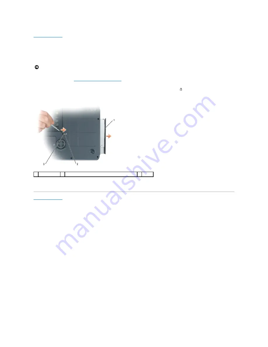
Turn the computer upside-down and remove the M2.5 x 8-mm device security screw labeled with a lock icon (

 ).  


3.

Insert a screwdriver into the indentation for the device security screw, and push the notch on the metal tab to release the drive from the bay.  


4.

Pull the drive out of the drive bay.  
 

Back to Contents Page


NOTICE: 

To help prevent damage to drives, store them in a safe, dry place when they are not installed in the computer. Avoid pressing down on them 

or placing heavy objects on top of them.

1  optical drive 

2  indentation for M2.5 x 8-mm security screw 

3  notch 

Содержание Precision M90

Страница 1: ...to refer to either the entities claiming the marks and names or their products Dell Inc disclaims any proprietary interest in trademarks and trade names other than its own Model PP05XA March 2006 Rev A00 Before You Begin Speakers System Components Subwoofer Optical Drive USB Port Board Hard Drive Processor Thermal Cooling Assembly Memory Module s Processor Module Modem Video Card Thermal Cooling A...

Страница 2: ...mm screws and lifting out the bay 8 Remove the screw in the battery latch assembly When you remove the screw the battery latch release on the bottom of the computer will also be removed CAUTION Before you begin the following procedure follow the safety instructions in the Product Information Guide NOTICE To avoid electrostatic discharge ground yourself by using a wrist grounding strap or by period...

Страница 3: ...h assembly into the channel on the computer base and press it into place 2 Using a small screwdriver hook the spring over the hook on the computer base 3 Place the battery latch release under the computer base line it up with the hole in the base and then replace the screw in the assembly Ensure that the newly installed latch moves smoothly and freely when pushed and released 4 Replace the hard dr...

Страница 4: ...5 Replace the system board and the four M2 5 x 5 screws 6 Replace in reverse order the other components that you removed in Removing the Battery Latch Assembly Back to Contents Page ...

Страница 5: ...uidelines to help protect your computer from potential damage and to help ensure your own personal safety 1 Ensure that the work surface is flat and clean to prevent the computer cover from being scratched 2 Turn off your computer see Turning Off Your Computer NOTICE To avoid losing data save and close any open files and exit any open programs before you turn off your computer CAUTION Before you b...

Страница 6: ...ve the battery from the bay 7 Turn the computer top side up Computer Orientation Screw Identification When you are removing and replacing components print the screw identification chart as a tool to lay out and keep track of the screws The chart provides the number of screws and their sizes NOTICE To help prevent damage to the system board remove the main battery before working inside the computer...

Страница 7: ...play Assembly 4 each Display Bezel 4 each under rubber display bumpers 4 each shoulder type under 2 screw covers and 2 rubber bumpers Display Panel 8 each Palm Rest 6 each top side 12 each bottom side Speakers 4 total 2 per speaker USB Port Board 1 each Fans 2 4 total 2 per fan System Board 4 each Hard Drive Bay 4 each ...

Страница 8: ......

Страница 9: ... following procedure follow the safety instructions in the Product Information Guide NOTICE To avoid electrostatic discharge ground yourself by using a wrist grounding strap or by periodically touching an unpainted metal surface such as the back panel on the computer NOTICE To help prevent damage to the system board remove the main battery see Before Working Inside Your Computer before working ins...

Страница 10: ...ard connector from the system board 9 Remove the four M2 x 3 mm screws that attach the ExpressCard cage to the top of the hard drive bay Back to Contents Page CAUTION Before you begin the following procedure follow the safety instructions in the Product Information Guide NOTICE To avoid electrostatic discharge ground yourself by using a wrist grounding strap or by periodically touching an unpainte...

Страница 11: ...the metal securing clips toward the back of the computer until the card pops up slightly c Lift the Mini Card out of its connector CAUTION Before you begin the following procedure follow the safety instructions in the Product Information Guide CAUTION Only products approved for use in your portable computer may be installed NOTICE To avoid electrostatic discharge ground yourself by using a wrist g...

Страница 12: ...nnector with the white triangle Connect the auxiliary antenna cable black to the antenna connector with the black triangle 6 Replace the Mini Card modem cover Back to Contents Page 1 securing clips 2 2 Mini Card NOTICE The connectors are keyed to ensure correct insertion If you feel resistance check the connectors and realign the card 1 securing clips 2 2 antenna connectors 2 3 Mini Card connector...

Страница 13: ...ee angle under the release latch and then push the battery into place b Connect the battery cable to the connector on the system board 2 Replace the keyboard see Keyboard 3 Replace the hinge cover see Replacing the Hinge Cover CAUTION Before you begin the following procedure follow the safety instructions in the Product Information Guide NOTICE To avoid electrostatic discharge ground yourself by u...

Страница 14: ...Back to Contents Page ...

Страница 15: ...otherwise noted each procedure in this document assumes that a part can be replaced by performing the removal procedure in reverse order 1 display assembly 2 hinge cover 3 keyboard 4 palm rest with touch pad 5 Mini Card 6 video card thermal cooling assembly 7 fan 8 hard drive bay 9 ExpressCard cage 10 hard drive 11 main battery 12 speakers 2 13 subwoofer 14 optical drive 15 system board 16 compute...

Страница 16: ...iodically touching an unpainted metal surface such as the back panel on the computer NOTICE Do not touch the processor die Press and hold the processor down on the substrate on which the die is mounted while turning the cam screw to prevent intermittent contact between the cam screw and processor NOTICE To avoid damage to the processor hold the screwdriver so that it is perpendicular to the proces...

Страница 17: ...e in reverse order beginning with step 5 Back to Contents Page NOTICE Ensure that the cam lock is in the fully open position before seating the processor module Seating the processor module properly in the ZIF socket does not require force NOTICE A processor module that is not properly seated can result in an intermittent connection or permanent damage to the processor and ZIF socket NOTE The pin ...

Страница 18: ...he part of the thermal cooling assembly that will cover the new processor a Remove the backing from the new thermal pad taking care not to tear the pad b Place the pad s adhesive side against the part of the thermal cooling assembly that will cover the new processor and press it into place 2 Place the processor thermal cooling assembly over the processor CAUTION Before you begin the following proc...

Страница 19: ...3 Tighten the four captive screws labeled 1 through 4 in consecutive order Back to Contents Page ...

Страница 20: ...nge Cover 6 Use the pull tab to disconnect the display cable from the system board and then disengage the display cable from the cable channel CAUTION Before you begin the following procedure follow the safety instructions in the Product Information Guide NOTICE To avoid electrostatic discharge ground yourself by using a wrist grounding strap or by periodically touching an unpainted metal surface ...

Страница 21: ...se of the computer so that they are accessible from the bottom of the computer 1 display cable pull tab 2 M2 5 x 5 mm screws 4 3 Mini Card antenna cables 2 4 display cable connector on system board 5 display cable in cable channel 1 Mini Card antenna cables NOTE When removing the display assembly carefully unthread the Mini Card antenna cables through the computer base and ensure that the plastic ...

Страница 22: ...nto the cable channel 6 Replace the hinge cover see Replacing the Hinge Cover 7 If a Mini Card is installed connect the antenna cables to the card see Mini Card If one is not installed tuck the antenna cables into their secured location 8 Replace the Mini Card cover Display Bezel NOTE The left hinge assembly has a small tab that you must first insert underneath the edge of the palm rest 1 tab ...

Страница 23: ...ottom of the lower right corner Then pull the bezel toward the right side of the display assembly to clear the tab on the side B of the lower right corner 1 shoulder screws 4 two at the top and two at the bottom 2 screw covers 2 3 M2 5 x 5 mm screws 4 one on each corner 4 rubber screw covers display bumpers 6 5 display bezel CAUTION Before you begin the following procedure follow the safety instru...

Страница 24: ...arting at any corner use your fingers to gently snap the bezel into place to secure it to the display panel 2 Replace the four M2 5 x 5 mm screws on the corners of the bezel 3 Replace the four shoulder screws and two screw covers 4 Replace the six rubber screw cover display bumpers around the bezel Display Panel Removing the Display Panel 1 display back cover 2 tabs 1 display bezel 2 display panel...

Страница 25: ...onnector and pull the top flex cable connector away from the display connector 8 Use the pull tab to disconnect the bottom flex cable connector from the inverter connector Replacing the Display Panel 1 display panel 2 M2 x 3 mm screws 8 3 display back cover 4 grounding wire and captive screw CAUTION Before you begin the following procedure follow the safety instructions in the Product Information ...

Страница 26: ...Computer 2 Remove the display assembly see Removing the Display Assembly 3 Remove the display bezel see Removing the Display Bezel 4 Slide the latch to the right and gently lift 5 Remove the spring that attaches the latch to the display panel Replacing the Display Latch 1 Replace the spring that attaches the latch to the display panel 2 Align the latch with the display panel and slide the latch to...

Страница 27: ... that connect the fan s to the system board 7 Lift the fan s out of the computer CAUTION Before you begin the following procedure follow the safety instructions in the Product Information Guide NOTICE To avoid electrostatic discharge ground yourself by using a wrist grounding strap or by periodically touching an unpainted metal surface such as the back panel on the computer NOTICE To help prevent ...

Страница 28: ...Back to Contents Page 1 fan for video card thermal cooling assembly if installed 2 M2 5 x 5 mm screws 2 3 fan cable 4 fan cable system board connector ...

Страница 29: ...lt and f to reset the computer defaults 5 Press Esc select Save changes and reboot and press Enter to save configuration changes 6 Remove the flash BIOS update program CD from the drive and restart the computer Back to Contents Page NOTICE Plug the AC adapter into a known good power source to prevent a loss of power Failure to do so may cause system damage NOTE If you use a BIOS update program CD ...

Страница 30: ... from the computer when the drive is hot do not touch the metal housing of the hard drive CAUTION Before you begin the following procedure follow the safety instructions in the Product Information Guide NOTICE To help prevent damage to the system board remove the main battery see Before Working Inside Your Computer before working inside the computer NOTICE To prevent data loss turn off your comput...

Страница 31: ...ing a Hard Drive to Dell Return your old hard drive to Dell in its original or comparable foam packaging Otherwise the hard drive may be damaged in transit Back to Contents Page 1 hard drive 2 foam packaging ...

Страница 32: ...ace snap the cover back into place starting from left to right Back to Contents Page CAUTION Before you begin the following procedure follow the safety instructions in the Product Information Guide NOTICE To avoid electrostatic discharge ground yourself by using a wrist grounding strap or by periodically touching an unpainted metal surface such as the back panel on the computer NOTICE To help prev...

Страница 33: ...the keyboard connector on the system board 7 Remove the keyboard Back to Contents Page CAUTION Before you begin the following procedure follow the safety instructions in the Product Information Guide NOTICE To avoid electrostatic discharge ground yourself by using a wrist grounding strap or by periodically touching an unpainted metal surface such as the back panel on the computer NOTICE To help pr...

Страница 34: ...age to components inside your computer discharge static electricity from your body before you touch any of your computer s electronic components You can do so by touching an unpainted metal surface NOTICE To help prevent damage to the system board you must remove the main battery see Before Working Inside Your Computer before you begin working inside the computer NOTE Memory modules purchased from...

Страница 35: ...er As the computer boots it detects the additional memory and automatically updates the system configuration information Back to Contents Page NOTE To get maximum performance dual channel memory bandwidth capability both memory module connectors must contain memory modules and the modules must be of the same size and configuration NOTE If a memory module is not installed properly the computer does...

Страница 36: ... on the system board 5 Disconnect the modem cable from the modem CAUTION Before you begin the following procedure follow the safety instructions in the Product Information Guide NOTICE To avoid electrostatic discharge ground yourself by using a wrist grounding strap or by periodically touching an unpainted metal surface such as the back panel on the computer NOTICE To help prevent damage to the sy...

Страница 37: ...e system board Align the connector on the bottom of the modem with the modem connector on the system board and press down on the right side of the modem 3 Replace the M2 x 3 mm screw Back to Contents Page NOTICE Ensure that the modem cable is routed correctly when you replace the modem ...

Страница 38: ... screw labeled with a lock icon 3 Insert a screwdriver into the indentation for the device security screw and push the notch on the metal tab to release the drive from the bay 4 Pull the drive out of the drive bay Back to Contents Page NOTICE To help prevent damage to drives store them in a safe dry place when they are not installed in the computer Avoid pressing down on them or placing heavy obje...

Страница 39: ...om the bottom of the computer CAUTION Before you begin the following procedure follow the safety instructions in the Product Information Guide NOTICE To avoid electrostatic discharge ground yourself by using a wrist grounding strap or by periodically touching an unpainted metal surface such as the back panel on the computer NOTICE To help prevent damage to the system board remove the main battery ...

Страница 40: ...ystem board 3 Reconnect the LED board connector to the system board 4 Replace the coin cell battery see Replacing the Coin Cell Battery 5 Replace the six M2 5 x 5 mm screws on the top side of the palm rest 6 Turn the computer upside down and replace the 12 M2 5 x 8 mm screws on the bottom of the computer 7 Replace the display assembly see Replacing the Display Assembly 8 Replace the keyboard see K...

Страница 41: ...Back to Contents Page ...

Страница 42: ...ideo Connector S Video TV Out Connector IEEE 1394 Connector USB Connector Video Connector S Video TV Out Connector Pin Signal 1 USB5V 2 USBP 3 USBP 4 GND Pin Signal Pin Signal 1 CRT_R 9 5V 2 CRT_G 10 GND 3 CRT_B 11 MONITOR_DETECT 4 NC 12 DDC_DATA 5 GND 13 CRT_HS 6 GND 14 CRT_VS 7 GND 15 DDC_CLK 8 GND S Video Pin Signal 1 GND ...

Страница 43: ...IEEE 1394 Connector Back to Contents Page 2 GND 3 DLUMA L 4 DCRMA L Composite Video Pin Signal 5 NC 6 DCMPS L 7 GND Pin Signal 1 TPB 2 TPB 3 TPA 4 TPA ...

Страница 44: ...oard 9 To remove the smart card reader pry up the reader by the metal screw plate and pull up and out from underneath the side tabs Back to Contents Page CAUTION Before you begin the following procedure follow the safety instructions in the Product Information Guide NOTICE To avoid electrostatic discharge ground yourself by using a wrist grounding strap or by periodically touching an unpainted met...

Страница 45: ...ector to the connector on the system board 2 Align the speakers on the screw holes for securing the speakers to the computer base 3 Replace the four M2 5 x 5 mm screws to secure the speakers in place two on each speaker 4 Re route the speaker cables into the cable guides and re adhere the tape to secure the speaker cables in place on the computer base CAUTION Before you begin the following procedu...

Страница 46: ...Back to Contents Page ...

Страница 47: ...the two captive screws that secure the subwoofer in place 8 Disconnect the subwoofer cable connector from the connector on the system board Back to Contents Page CAUTION Before you begin the following procedure follow the safety instructions in the Product Information Guide NOTICE To avoid electrostatic discharge ground yourself by using a wrist grounding strap or by periodically touching an unpai...

Страница 48: ...rd 7 Remove the hinge cover see Removing the Hinge Cover 8 Remove the keyboard see Keyboard 9 Remove the display assembly see Removing the Display Assembly 10 Remove the palm rest see Removing the Palm Rest 11 Disconnect the ExpressCard connector from the connector on the system board CAUTION Before you begin the following procedure follow the safety instructions in the Product Information Guide N...

Страница 49: ...e Video Card Thermal Cooling Assembly 19 Remove the processor thermal cooling assembly see Removing the Processor Thermal Cooling Assembly 20 Remove the processor see Removing the Processor Module 21 Remove the docking frame a Remove the two docking frame screws b Lift the docking frame away from the system board v Remove the four M2 5 x 5 mm screws from the system board 1 USB port board connector...

Страница 50: ... the flash BIOS update program CD that accompanied the replacement system board into the optical drive Follow the instructions that appear on the screen See Flashing the BIOS for further information 4 Enter the system setup program to update the BIOS on the new system board with the computer Service Tag Back to Contents Page 1 system board M2 5 x 5 mm screws 4 1 system board assembly NOTICE Before...

Страница 51: ...t Dell the DELL logo and Dell Precision are trademarks of Dell Inc Microsoft and Windows are registered trademarks of Microsoft Corporation Other trademarks and trade names may be used in this document to refer to either the entities claiming the marks and names or their products Dell Inc disclaims any proprietary interest in trademarks and trade names other than its own Model PP05XA March 2006 Re...

Страница 52: ...ard out of the computer Replacing the USB Port Board 1 Insert the notch on the USB port board under the small tab on the computer base and the other side of the board over the pin 2 Replace the M2 5 x 5 mm screw CAUTION Before you begin the following procedure follow the safety instructions in the Product Information Guide NOTICE To avoid electrostatic discharge ground yourself by using a wrist gr...

Страница 53: ...board 4 Replace the palm rest see Replacing the Palm Rest 5 Replace the display assembly see Replacing the Display Assembly 6 Replace the keyboard see Keyboard 7 Replace the hinge cover see Replacing the Hinge Cover Back to Contents Page ...

Страница 54: ...ign the video card thermal cooling assembly over the connector on the system board and press down CAUTION Before you begin the following procedure follow the safety instructions in the Product Information Guide NOTICE To avoid electrostatic discharge ground yourself by using a wrist grounding strap or by periodically touching an unpainted metal surface such as the back panel on the computer NOTICE...

Страница 55: ...2 Tighten the four captive screws on the video card thermal cooling assembly Back to Contents Page ...

Отзывы: